1776 Opto-Tron w/adj LED


|
This post was updated on .
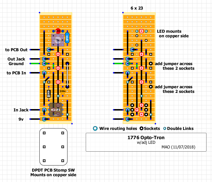
I hadn't planned on posting this as it's specifically for a 125B and a bit of a bugger, but GrooveChampion asked for it so here goes.
I would probably recommend the PCB from 1776 as it would be much, much easier than what I have here... As for the Opto-Tron circuit, it's simple and pretty awesome noiseless bypass. Now that I have been using it, the clicks and pops from a standard bypass seem much more noticeable.  May never go back, thanks to Josh! May never go back, thanks to Josh!  And as for this layout, I designed it specifically for a 125B and this DPDT stomp switch. I kept the size to the short width of the switch so it would not interfere when using a battery. The LED lines up nicely at just the right distance from the stomp switch, although you could easily run wires from the layout and mount the LED anywhere. The 23 rows was just for aesthetic reasons, to fill the width of the 125b. The top 3 rows aren't being used and can be trimmed off. A couple challenges need mentioning: Both the LED and the Stomp Switch mount on the copper side of the board which requires some "backwards" soldering. And the pins of this particular stomp switch are larger than the stripboard holes. They also need some "encouragement" to line up properly. What I have learned after doing it a few times is that its best to file down the stomp switch pins so they easily fit into the existing stripboard holes. Enlarging the holes doesn't leave enough copper to get a decent solder joint. Better to file down the pins, about half of their length as you need room between the switch and the copper side of the board so you can solder it in (the switch mounts to the copper side). Filing them halfway down helps position the switch away from the board...you'll see what I mean if you try this. A needle tip on the soldering iron is probably a must as it's a tight space to solder in. I would also recommend soldering in the LED after the populated board is fitted into the enclosure, so you can get the proper lead length. This isn't necessary if you run wires to the LED rather than soldering it directly to the board, which is recommended when using a bezel to mount the LED to the enclosure. I have found there is enough lead length to mount the LED on the copper side of the board and have it extend outside of the enclosure. Having the LED poking through without a bezel is much easier to manage. If using a bezel, I would suggest running wires to the LED from the board rather than direct mounting as it's difficult to set the bezel after the LED has been soldered to the underside of the board (ask me how I know) And I also wanted to be able to adjust the LED brightness with a trimmer based on color/type used. So the 1k8 resistor is there to prevent accidentally frying the LED or maybe the H11F1 if the trimmer was maxed out. I wasn't sure how bright the LED would be so I used 1k8 to limit the brightest setting. It's probably safe to use the standard value 1k. edit: 1k is safe according to the BOM doc And last thing to mention there is a link that spans across 2 of the stomp switch pins, the white link on the right side of the board. Rather than risk that link shorting to the switch I use sockets to raise the link above the pins. So, as I mentioned, probably better off purchasing the PCB from 1776 And you'd need to use this switch instead. FWIW, next time I need to add an external charge pump, I'm considering a version of the Opto-Tron that will include an onboard charge pump. If any interest I'll post that one too for those stripboard diehards like me  if/when realized. if/when realized.
 Here is a picture of the 1st one I built, installed, before figuring it out it was better to file down the pins. I had enlarged the holes just a bit to fit the non-filed switch pins. You can't see it, but I ended up having to extend the link leads long enough to wrap around the pins of the switch as there wasn't much copper left to solder to. I then soldered the switch pins to the link leads which were already soldered to the board...Although that was a little easier than soldering directly to the board, not recommended! File the pins down instead...or better yet, purchase the PCB. You can also see the stomp switch pins poking out of the board, and the raised link spanning 2 of those pins, in this case was a black wire which I eventually soldered to the sockets. 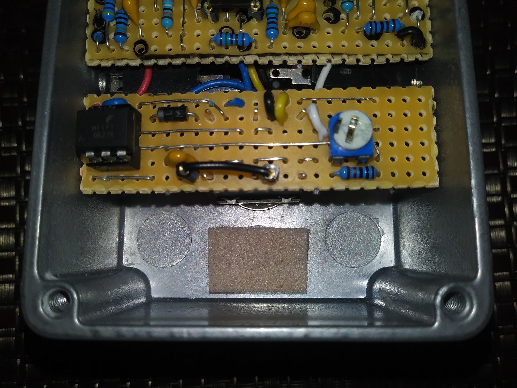
1978 Gibson Les Paul Standard, Cherry Sunburst
|
|
|
I see why I am better off buying the PCB's, but still interesting to build.
Are there any advanteges to this over a mechanical true bypass switch? |
|
|
This post was updated on .
Yeah, the 1st time will be a bit of a pain, but you'll learn quickly on what to do the next time.
As for advantages: With your amp cranked up, you don't hear any click or pop when engaging the Opto-Tron switch. A good choice for any effect you turn off and on within a song. Not really needed if you keep the effect engaged all or most of the time. Total DIY cost is about $4.50 in parts, or $7 if you go with the PCB (you'll need this DPDT with the pcb). That's pretty good for noiseless switching. With this layout you can easily adjust the LED's brightness as the trimmer is accessible. And I think it looks kinda cool as it hides the jack and switch wiring :0) Disadvantage? One thing to mention which is in the build doc, when bypassed the Opto-Tron is true bypass, when engaged there is a small added resistance at input (300 ohms). To me, that's not a bad thing.
1978 Gibson Les Paul Standard, Cherry Sunburst
|
|
|
Here's another version laid out specifically as a topper for this switch
Much, much easier than the 1st one. It sits right on top of the switch, the wires route between the switch lugs and there is enough room to easily wrap the wires around the lugs for added protection again the board shorting to the switch. Pin 3 of the IC needs to be lifted or cut. ( I used 5 sip sockets and just let pin 3 dangle) You can use a socket for the IC with a 125B. Without a socket, it looks like it will fit in a 1590BB, but I haven't tried that yet. 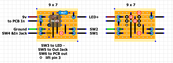 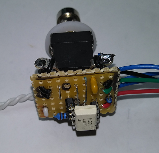 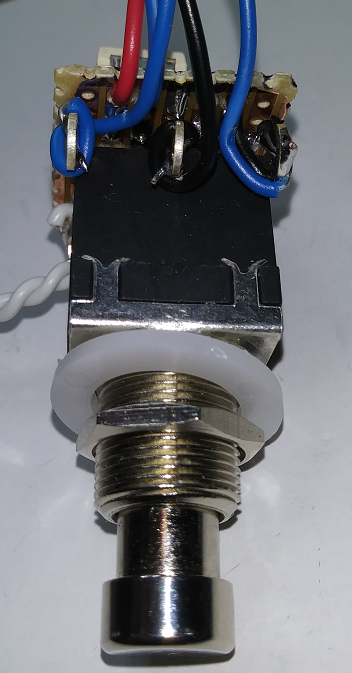
1978 Gibson Les Paul Standard, Cherry Sunburst
|
«
Return to Compressors
|
1 view|%1 views
| Free forum by Nabble | Edit this page |