Hi Matt.
There's a few ways do do it and each have their pros and cons.
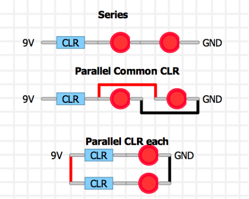
With Series
9V is presented to the CLR, but the resistor voltage drop may see something like 8.5V presented to the first LED. The drop through the first LED might be something like 1.2V so. the second one sees 7.3V. The overall result is one LED brighter than the other. You can test different LEDs to minimise this effect. And of course, if one LED blows, the other doesn't see voltage.
Parallel With Common CLR
Both LEDs see the same voltage but current is divided among them, again based on the voltage drop of each LED so again one looking brighter than the other could be a problem. Matching LEDs can help here.
Parallel with CLR Each
Both LEDs brightness can be tuned by changing their CLR values as one now does not affect the other. The problem is that the current consumption now increases which will drain batteries faster, or add to the limit of your daisy changed PSU.
Ultimately what I'm getting at is...there are many different ways to do this but only you can choose whats best for your requirements.
As for the PCB...It will work fine for the series and parallel example (you just daisy chain the LEDs and return the last cathode to the PCB). But with the Parallel with own CLR example you would have to hang multiple resistors off one pad and fly wires all over the place. Probably best to make a daughter board on vero for that.
I should also mention that the PCB has arranged the LED and its CLR as...9V > LED > CLR > GND. It doesn't matter whether you place the CLR before (my example) or after (the PCB) the LED. Functionally the circuit is identical.
Good luck

