Loading... |
Reply to author |
Edit post |
Move post |
Delete this post |
Delete this post and replies |
Change post date |
Print post |
Permalink |
Raw mail |
![]() ![]() ![]() ![]() ![]() ![]() ![]() |
4 posts
|
This is a modified layout based on the 3 Channel Splitter/Mixer layout created by IvIark found
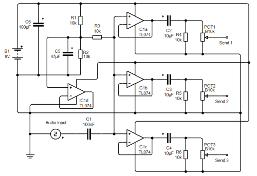
 here
This layout just splits a single input audio signal into 3 buffered output signals and omits the mixer circuit from the original layout. Volume controls can be added to each output using a standard potentiometer as shown (Note that in the layout the pot shaft is facing you, and with that pinout turning it clockwise increases volume). The original circuit calls for linear taper pots, but logarithmic pots may be more suitable for volume controls. The value of the 100nF capacitor may require adjustment depending on the type of instrument or audio signal input. Lower capacitances will filter out bass frequencies further, while higher capacitances will let more bass through. As rough values I'd say avoid going go below 22nF or above 470nF but if I get a chance I may experiment and runs some tests. As the remaining op-amp is not used, this layout could be further adapted to a 4 Channel Splitter. There is also scope to create a layout for a 2 Channel Splitter using an 8 Pin Op Amp. If either of these would be of interest, leave me a comment. Please note this layout is unverified and as this is my first upload here, I anticipate issues. If I find the time, I will build one myself to verify and run some tests. Layout: ![]() 
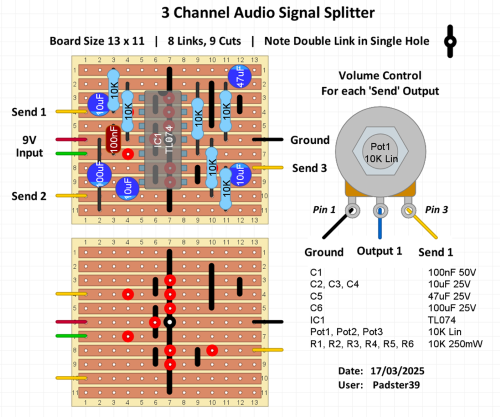
Reverse board (for the Cuts): ![]() 
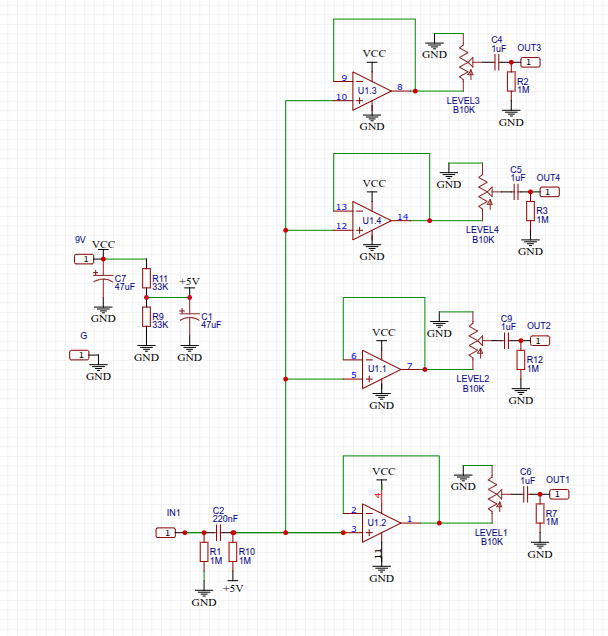
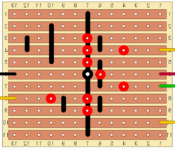
Schematic: (is the least I could produce given it's modifying an existing layout) ![]() |
Loading... |
Reply to author |
Edit post |
Move post |
Delete this post |
Delete this post and replies |
Change post date |
Print post |
Permalink |
Raw mail |
![]() ![]() ![]() ![]() ![]() ![]() ![]() |
1 post
|
Hello, Padster,
I have built this using your layout and it is working without any issues. I have put this in a 1590A, without volume controls and using 3.5mm jacks! Earlier, I built IvIark's version, left out the mixer section; and as user Ashcroftt mentioned, he was using it as a splitter only with a 33k put between pin 13 and GND, although I was not using the master output it fixed one issue which was no signal through any of the sends, weird. But still that had some noise and hum in the outputs. Thank you. You can tag this as verified. |
Loading... |
Reply to author |
Edit post |
Move post |
Delete this post |
Delete this post and replies |
Change post date |
Print post |
Permalink |
Raw mail |
![]() ![]() ![]() ![]() ![]() ![]() ![]() |
Administrator
1709 posts
|
Great stuff, nice job both of you 👍🏻
|
Loading... |
Reply to author |
Edit post |
Move post |
Delete this post |
Delete this post and replies |
Change post date |
Print post |
Permalink |
Raw mail |
![]() ![]() ![]() ![]() ![]() ![]() ![]() |
4 posts
|
In reply to this post by mr20807
Excellent work! I'm glad to hear that it's working without any issues or noise and that it fits in a 1590A. I'm glad I took the time to check it out.
I suspect the reason the send outputs wouldn't work at all without the mixer section is due a lack of reference at the outputs of each op-amp. With the mixer section in place, all three outputs eventually find a reference to ground through the channel pots, or else the final 10k resistor between Output and Ground. It sounds like you had neither of these in place initially. I'm not completely sure why the 33k resistor between pin 13 and ground would fix this, it may simply be a different issue where the bias voltage was destabilised by the floating op-amp (at pins 12, 13, 14) and adding the 33k resistor stabilises the differential Voltage at that op-amp. Perhaps that fixed an issue with the bias Voltage connected at pin 12, but this is conjecture and it's difficult to say for sure without testing. Anyway, enough of me waffling. Thank you for building it and letting me know it’s verified. All the best |
Free forum by Nabble | Edit this page |