A few definitions _ Overdrive, Boost, Fuzz, Distortion

classic Classic list List threaded Threaded
25 messages Options
12
Reply | Threaded
Open this post in threaded view
|

Re: A few definitions _ Overdrive, Boost, Fuzz, Distortion

motterpaul
Thor - I need help!  I am getting a ton of hiss on the Thor - did you get that? The only person in the comments who says he did not get his used 5458s (which I just happen to have on order) instead of 5457s.

The problems seems to be with J201 biasing but not sure.

http://2.bp.blogspot.com/-5HrpFhm9x8U/UOCQmgY8BiI/AAAAAAAAAWo/jYtDIkz1v38/s1600/ROG-Thor.png


Reply | Threaded
Open this post in threaded view
|

Re: A few definitions _ Overdrive, Boost, Fuzz, Distortion

Silver Blues
You could try measuring your FETs, using the Fetzer Valve calculator and tweaking some resistor values and see if that works.
I actually replicated the calculator in Excel so I'd have it all the time, it seems very useful. Whenever Frank puts up his spreadsheet I'll merge the two into one super JFET calculator
Through all the worry and pain we move on
Reply | Threaded
Open this post in threaded view
|

Re: A few definitions _ Overdrive, Boost, Fuzz, Distortion

Frank_NH
In reply to this post by motterpaul
Someone called??

I also had hiss when I attempted the vero version.  I think part of the problem may be in the layout, but I can't be sure.  Having said that, I would move that 100 uF cap away from Q2, perhaps under the cut in column 13.

As for biasing, I did a calculation for you in my spreadsheet (here's an image):


I used 201 JFET data for Vp ~ -0.91 V and Idss ~ 0.64 V.  For Vdrain = 4.5 V, I get a drain resistor value of 15K.  Now your trimmer is only 20K, so you don't have much wiggle room.  In fact if your JFET's Vp is much lower than -0.8V, you probably can't bias the JFET!   So, two things you can try:

(1) change the trimmer to 50K, or
(2) use a JFET with a Vp ~ -0.9V or more (using your handy dandy JFET Tester to find the magic JFET ).

You can also try a 2N5457 instead of the J201, but it won't have the same gain.

Hope you can get the problems sorted.  Let us know how it goes - and start a new topic as I'm sure there will be a lot of interest in this...
Reply | Threaded
Open this post in threaded view
|

Re: A few definitions _ Overdrive, Boost, Fuzz, Distortion

motterpaul
Thank you so much! It will take me some time to sort out your work - but if I get that working I will start a new thread.

My JFet tester is pictured below. I cannot figure out how to get the readings I need. I do not see anything wrong with the way it is made compared to the non-IC version posted.  One thing i have tried is just powering up the tester and using my + probe on the Source & Gate and I can get readings that look like they could be close - but I am not sure.

By the way - I hate to admit it but I have already blown up 3 J201s (over a few days) because I keep getting confused about the pinout. I check it, but my mind has problems with the "mirror image" effect where I try to see something "backwards" and for some reason I still get it wrong.

Funny - the only time I got a reading that looked like a real J201 Idss (in the 600 range) it turned out I had it backwards - kaplow. So, I turned the next one right side around and the readings are in the 200 range - so, I don't know if its me or the JFets - probably me.

Yeah, I was so thrilled to be getting the 5457s thinking they would be better than J201s, and they aren't. Now I have had to order more J201s.

BTW, I also thought the trimmer seemed to low for the THOR J201. But the squeal, trebly sound is unreal. It sounds like an out of phase Fender Squire through a radio shack transistor radio.


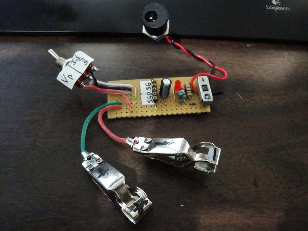
FYI: there is nothing between black & red wires on the switch (just looks like it), and the LED/CLR is on its own, just there to tell me its on. The S & G are each linked to the other S & G, 9v goes to the drain.
Reply | Threaded
Open this post in threaded view
|

Re: A few definitions _ Overdrive, Boost, Fuzz, Distortion

Frank_NH
Paul,

You have your switch label backwards, I believe.  Swap it around and you should be good to go.

Here's how to use it.

(1) Insert the JFET, minding the pinout.
(2) Set up your DMM with the clips and turn it on.  Set it to read DC volts.
(3) Switch the tester to the Idss mode.
(4) Turn on the power, and look at your DMM.  It should read a voltage like 0.0656 V (or 65.6 mV) for a J201 (it will be higher for other JFETs).  Multiply this voltage number by 10 and that is you Idss in mA.  In the example we would have 0.0656 x 10 = 0.656 mA.  Record this value (spreadsheets are great for this!).
(5) Flip the switch to the Vp mode.
(6) Read the voltage.  Let say this is 0.93 V.  This is the Vgs(off) value (though the Fetzer article still uses Vp and I use that designation too) - it is really a negative number for biasing applications, so I record this as -0.93 V.  Again this voltage will be higher for other JFETs.  To get a feel for the numbers, look at the end of the Fetzer article, where they list several JFET types and the typical ranges of Idss and Vp.

Go ahead try some JFETs and let us know what numbers you get.  Good luck.
12