About grounding


|
SO, having no knowledge on theory, when I first started soldering (about a year ago) I had trouble wrapping my head around ground usage. Took me a while to understand that it doesn't really matter what I do, as long as the ground is connected. Is that so? Usually I take double wires from the dc input, one goes to vero, one goes to everything else. I think that works great, and never had any trouble with it.
Going through various designs around the site, I stumbled upon the Rusty Box and its complicated (to me) power supply. The ground is colored orange in the "rusty voltage converter" vero, witch got me thinking it is different than the others. Again, trough some pics of John K's builds I found, I traced the ground to be common. (last comment on the page) So I was now convinced that the order doesn't matter, and that all ground is common. Nevertheless, I have to ask. I am now using the huminator in almost everything I build, and try to build it on the same vero as the effect. Here is my Naga Viper, the bottom three rows are the huminator: 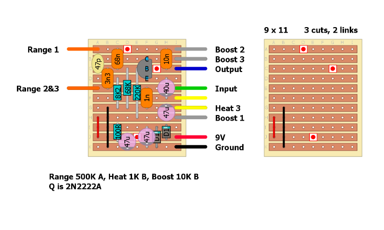 Now I've been wondering if it is of any significance to use the output ground of the huminator or not. Can I still use the second wire from my dc input for everything else in the enclosure, or should I draw it from the circuit? Also, while I'm at it, the same question goes for Led powering. 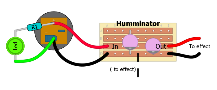 Can i connect the led directly to the 9v or should I connect it on the filtered end?Will that get unfiltered current in my circuit? The line marked (to effect) goes to the previous question. Can I get ground from there, or I have to take it from the end of the huminator? I tend to write many things to get to my point, sorry about that, I hope someone can read through it, even if it seems silly. Thank you! |
|
|
This post was updated on .
"Took me a while to understand that it doesn't really matter what I do, as long as the ground is connected. Is that so?"
Correct. "Going through various designs around the site, I stumbled upon the Rusty Box and its complicated (to me) power supply. The ground is colored orange in the "rusty voltage converter" vero, witch got me thinking it is different than the others." Different, only in the sense that the wire on the layout is orange - it could just as easily be coloured black. The real difference is that it supplies both positive and negative voltage, but you treat the ground wire exactly the same as any other pedal. "So I was now convinced that the order doesn't matter, and that all ground is common." I believe that this is not always strictly true - common could be set at a voltage other than zero. Better to think of ground as ground, rather than common. Your layout is good - you only need one ground wire as you have used link wires to join the two circuits. I'm not sure what you are asking in regard to the LEDs - I don't understand quite what you are getting at there, I'm afraid, so I don't have an answer for you on that point. Basically all ground points need to join up somewhere. If it helps, I always "star" ground mine to the output jack ring (ground) lug. I'm pretty sure most of us do it that way too. EDIT: I need to clarify one point though - remember the battery black (ground) wire runs to the input jack sleeve, and the LED black (ground) wire runs to the 3PDT switch, then onto the output jack ring lug. Also it's possible to star ground from different points. some builders star from the ground row on the board (if there are spare holes to take the extra wires). Some builders like Travis, use a ring connector screwed to the inside of the enclosure as a star point, then just run one ground wire to the output jack. |
|
|
Thanx for the quick reply Beaker!
By "star" you mean that everything goes from and to the lug as needed I suppose. Kind of a "ground central". About the led. Not so much a ground question I guess. If I use unfiltered voltage (that isn't coming form the huminator output) for the led, can that cause noise? In my mind the 9v goes through the led, gets used (and maybe abused  ), and then drains into the ground. Is that gonna produce noise since it wasn't filtered? ), and then drains into the ground. Is that gonna produce noise since it wasn't filtered?
|
|
|
Yes, like spokes on a wheel. (I have just ediited my post while you were replying, so worth reading again.)
Now I understand about the LED, but no, I don't have an answer for you, as I don't know myself. |
|
|
This post was updated on .
The led is best fed from the power rail before any filtering.
Almost all simple power filters are first-order low-pass filters, because we want to strip away everything but 0 Hz (aka DC). The main source of power noise is 60 Hz bleed-through from the AC supply along with its harmonics (120 Hz, 180 Hz, 240 Hz, etc.), so we try to use RC values that give a corner frequency below 60 Hz. Another source of noise is the led. They don't usually generate noise in operation unless they are damaged, but when they are switched on they cause a sudden surge of current from V+, through the led, into ground. That surge can sometimes manifest as a click or pop. Clicks and pops contain a wide range of frequencies, but the higher frequencies will be most audible. So we want to filter the power after the led to get remove the pop before the DC voltage reaches the audio path. It's more important in some circuits than others, but it's good practice to always do it that way. If you look at the huminator schematic, that is exactly how it is designed.  Edit: I didn't see your images earlier because I'm on vacation and my internet connection is pretty bad, but the image finally loaded, and I notice two things: 1. You are using both parallel and series diodes for polarity protection. This is overkill. If the circuit can handle the voltage drop ftom the series diode, then just use that. Parallel diodes used alone will usually damage either the circuit board, the power supply, or both, if you ever connect a reverse polarity adapter. In your case, the parallel diode comes after the series diode, so it can never actually do anything. Save yourself a diode. 2. You have a 47 uF cap just after the protection diodes, then a 100R, then another 47 uF cap. The 100R and the second cap are your low-pass power filter. The first cap isn't doing much of anything. Without the resistor in front of the cap, the filter is relying on the resistance of the wire and the intrinsic resistance of the supply and the series diode to determine the corner frequency of the filter. Since this resistance is pretty low, the corner frequency will be pretty high for supply filtering. Without the resistor and the other cap, it's better than nothing. But since you have the resistor and the other cap, you are essentially just wasting a cap. There, two less components with no hit on performance. Edit again: Your huminator daughter board doesn't do anything as drawn. There's no series resistor, and neither cap appears to be connected to the positive rail. |
|
|
Seer knowledge rain!
Thanks for taking time from your vacation (hope you're having a good time!) Now, I use the huminator just as I've seen it here, again, I don't really know what I'm doing lol. I just place the components differently to fit my builds.  There is the huminator as posted by Neil McNusty here (notice this is presented as the "Huminator II") 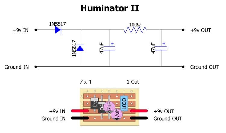 That is the design I've been using (didn't really looked anywhere else to find out more, I assumed that was a functioning layout). Now, a google later, I've found this that suits your schematic. 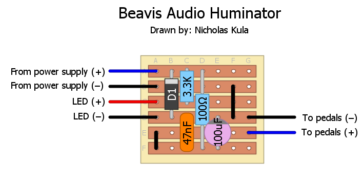 So, what you're telling is that the layout I've been using is redundant? Also, am I to understand that for the LED I should use 9v before filtering but ground "after" filtering? In general, the ground used around the build must be the one from the huminator board and not directly from the souce? (sorry for using so many images, ruining induction's vacation) :D |
|
|
Judging by those layouts it shouldn't matter if the ground is taken from the huminator boards or not. No filtering or whatsoever of the ground signal is taking place, it travels in a straight line through the boards. Nor could it be, otherwise it would not be grounded. Methinks its just being provided from the boards for convenience. Might save you a wire depending on how you wire your pedal. Because the less wires you have to use, the better.
|
|
|
In reply to this post by Zanius
Yes, the diode from 9V to ground is redundant and the 47u from 9V to ground is redundant. Neither will hurt anything, but you don't need them. Neil's design will function just fine, but there's no benefit from using components that don't do anything. 9V for the led should come as close to the supply as possible. Ground for the diode should also be as close as possible to the supply. The surge of current from turning the led on or off travels through the led and its ground wire, and goes back to the adapter. That surge can create a sudden temporary disturbance in the ground potential wherever that current runs, and that disturbance can sometimes be heard if the audio path connects to a ground wire where that current runs. Visually trace the loop of that current (psu+ -> clr -> led -> ground -> psu-, including all copper wires and traces), and make sure no audio components connect to ground along that loop. If you attach the led subcircuit directly to the psu, and the audio ground further away, you should be fine. The exact same logic should be used for lfo's and any other source of voltage transients, including supply ripple. So in an ideal layout, you'd attach the filter caps to ground near the the psu as well (closer to the psu than the audio ground path, but further away from the psu than the led ground). This will keep the audio ground as clean as possible. In practice, you usually won't hear a difference, except maybe in very high gain circuits. Not ruined at all. I like thinking about this stuff, even on vacation. Typing on my phone is a PITA, but that's not your fault. |
|
|
One thing to keep in mind with these power conditioners is that the series diode and 100 ohm resistor will result in a voltage drop from 9V. For example, if you effect is pulling 5 mA, then there will be a 0.5V drop across the 100 ohm resistor alone. You can up the big cap to 220 uF and drop the resistor to 50 ohms and get the same filtering but with less voltage drop. The only drawback is that larger uF caps are physically bigger.
|
«
Return to Open Chat
|
1 view|%1 views
| Free forum by Nabble | Edit this page |