Adding and LED to Floating Ground Circuit
|
Administrator
|
So I've been working on playing with the ESR graphic fuzz, which I understand is a floating ground circuit, similar to a PNP. I get everything to work perfectly, but I want to add an LED so I know the pedal is one instead of playing a guessing game during a show. How can I add it? I tried first buy following the offboard here, but no dice. I even tried connecting it from the switch to the -9V, still nothing. What leg goes where?
|
|
It may be too early in the morning for coherent thought (especially since you say you followed Mark's offline wiring diagram) but... There's gotta be a +9V potential in that circuit someplace... If you are using a 3pdt footswitch, take the 9V to a resistor, then to the led anode, cathode to footswitch pole, other pole to ground (just mind which throw is on/off). Or am I missing something (entirely all too possible)? |
|
In reply to this post by rocket88
The ground in the ESR is not floating, it's tied to the half rail of the battery. That means the positive side of the battery is at +4.5V and the negative side is at -4.5V. (This is why you can't use a normal adapter to power this circuit.) The voltage drop (Vf) of the led and the amount of current (I) required to light it vary by led so I can't analyze yours in particular unless you have some specs, but a standard led will drop between 2 and 3.5 V, and will need about 20 mA of to light up to full brightness. I also don't know what current limiting resistor (clr) you used on your led, so the following is approximate:
Red led: Vf = 2V, clr = 1k. V = 4.5V supply - Vf = 2.5V. I = V/clr = 2.5mA. That is probably not enough current to light the led. Try a 100R clr. Blue/white led: Vf = 3.5V, clr = 1k. V = 4.5V supply - Vf = 1V. I = V/clr = 1 mA. That is definitely not enough current to light the led. Try a 47R clr. If your battery is less than fresh, it only gets worse. If this is indeed the problem, you could also try a low current led instead, but there's a simpler solution so you don't have to trade out parts. Instead of tying the cathode of the led to ground (through the switch), try tying it to the negative terminal of the battery (through the switch). Then you have 9V to work with and your usual clr and led combination will behave as expected. Of course it's also possible you put the led in backwards or something. |
|
Great stuff, Induction!  Also good to know I wasn't completely off base 
|
|
Administrator
|
Thanks for the help. I was reading somewhere about it and they said it was a floating ground, but apparently they were wrong. Still a little new to this, so I'm trying to learn as much as I can. I've tried a few different LED's all were water clear. I tried white, blue, and green with a 2k2 resistor. What I meant about following Mark's offboard, is that I had attached the positive leg of the LED to the resistor which was board on the +9V, and the negative leg of the LED is connected to the switch. But when the switch is turned on the LED does not go on, but the circuit does. If that makes more sense.
|
Probably a superfluous question (not related to this specific circuit but to Mark's diagram) but you don't mention whether you grounded the middle and the other outer lugs of that pole? The circuit needs to be completed... I'm not trying to be a smarta**, I've forgotten my share of grounds so I'm just checking... |
|
Administrator
|
Haha Goran, I've forgetten the ground a few times, in fact most times I've had a circuit have problems my ground is messed up somewhere. But yes, the board ground is connected to the middle lug, and rest of the switch grounds are connected to the enclosure by the jacks. The positive and negative of the power is connected to the board in the proper locations.
|
|
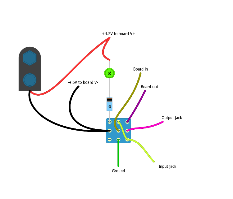
Remove the ground connection from the led part of the switch and replace it with the lead to the negative battery terminal. Make sure there is no connection between the negative battery terminal and ground. The ground from the board should connect to the input and output jack grounds, but not to the battery or led. It should look something like this if you're using IvIark's offboard wiring:
 This should get you sorted, though I'm making some assumption since I don't know what layout you used. There are some bad schematics for this circuit floating around out there. Let us know if it works. |
|
Administrator
|
Thanks Induction. If you want I can post the layout I'm using. Peeps posted it here awhile ago, and works perfectly. I'm going to give this a try and let you know how it works out, it may take awhile, as I don't have the time at the moment to mess with it. Might just try to make another one like this, instead of redoing the whole wiring. I want to do some messing around with it like Jimmy Behan, but not quite sure where cuts have been made for these components to be added, not to mention I believe he figured out how to tweak the circuit so it can be daisychained too.
|
«
Return to Open Chat
|
1 view|%1 views
| Free forum by Nabble | Edit this page |

