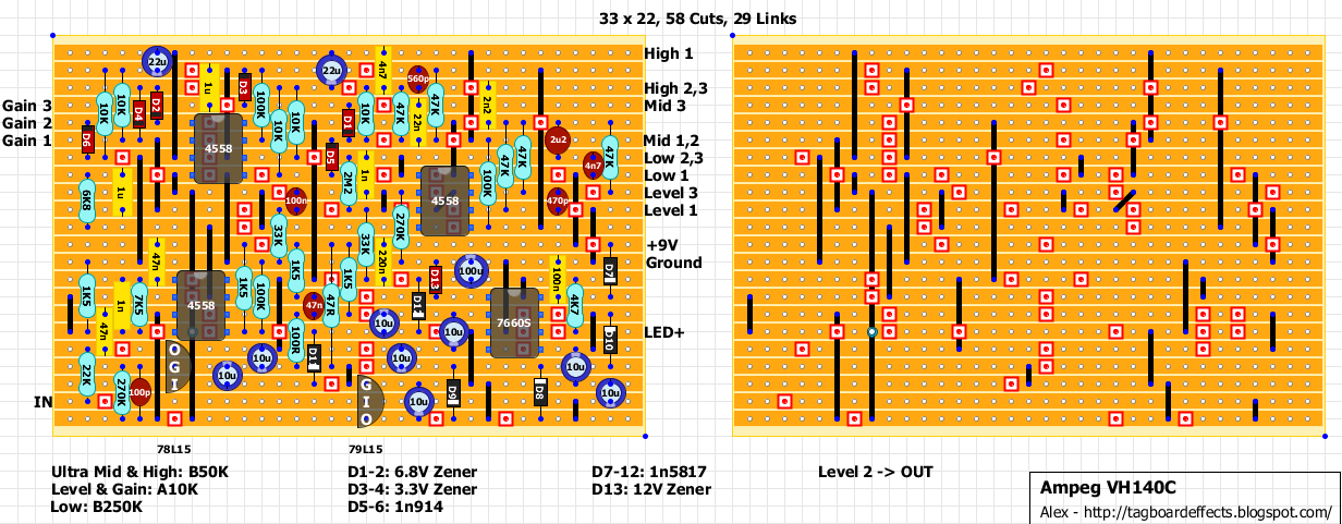
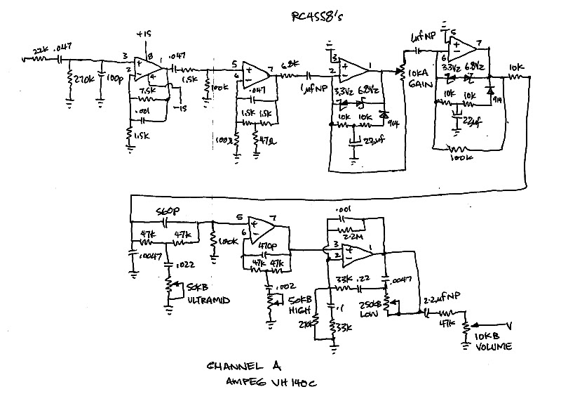
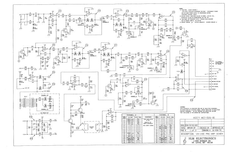
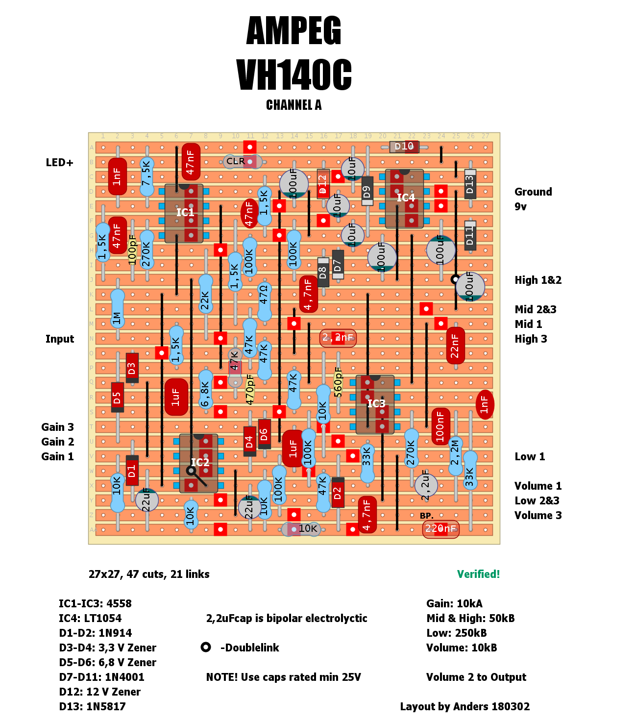
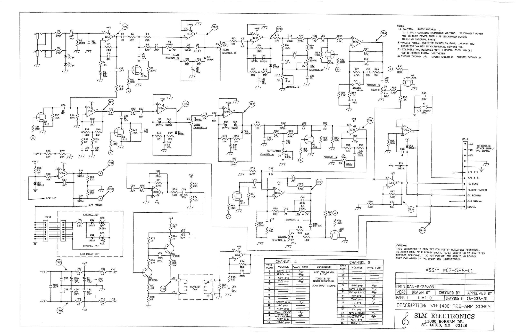
Ampeg VH140C

classic Classic list List threaded Threaded
37 messages Options
12
Reply | Threaded
Open this post in threaded view
|

Ampeg VH140C

Alex
This post was updated on .
This was a request from an unknown schematic.
Not sure about pots orientation.
I've added a bipolar voltage converter with voltage regulators to achieve the +/- 15V this circuit needs.
Hope it works!
Reply | Threaded
Open this post in threaded view
|

Re: Ampeg VH140C

Hozy31
The man's a genius
"Red velvet lines the black box"
Reply | Threaded
Open this post in threaded view
|

Re: Ampeg VH140C

TheChaplain
In reply to this post by Alex
This is killer! From what I'm seeing the part values match the schematic.

I wanted it to act more as an added amp channel more than as a distortion pedal sort of like what the Van Weelden Royal Overdrive does. I miss my VH140C like crazy but I sold it because it really only does one tone well and that doesn't cut it for me.

For what its worth, according to the service manual:
D1-2 = 1N754
D3-4 = 1N5393
The journey will answer questions that, in the beginning, you never thought to ask.
Reply | Threaded
Open this post in threaded view
|

Re: Ampeg VH140C

strassercaster
In reply to this post by Alex
very nice layout. i had one for a while . i loved it but it didnt cut through the mix. great for playing satriani and vai .i loved the clean channel too. i am friends with several of the st louis music engineers. when i was building my first tagboard chorus pedal and getting lfo tick one of them told me the original prototype had the same issue it delayed production  and the first run had to have revisions / mods done on the assembly line.

Crate actually applied for patent for the assymetrical diode clipping with zeners. at the time boss had the assymetrical patent for it via the super overdrive. ibanez sued and won some years ago . its funny i was checking one out on craigslist today .man i have a bench full of half built pedals some waiting for chips others waiting for boxing .if someone doesnt verify this soon i will . i a
was wished this amp had a tube power section for more punch. ill bet it will sound killer on my low input  jmp marshall for some extra punch in the mix.Alex your the superstar pumping them out "
Reply | Threaded
Open this post in threaded view
|

Re: Ampeg VH140C

TheChaplain
In reply to this post by Alex
built it and I'm not getting anything to come out. I measured the 7660S:

Battery- 9.41v

1- 8.98
2- 5.16
3- .3mV
4- -3.64
5- -8.6
6- 4.13
7- 5.59
8- 8.98

The journey will answer questions that, in the beginning, you never thought to ask.
Reply | Threaded
Open this post in threaded view
|

Re: Ampeg VH140C

TheChaplain
In reply to this post by Alex
Ok ok ok, first off:

VERIFIED  

The circuit does work but mine sounds a bit chunky and off.

For the diodes:
6.8vz = 1N5235BTR
3.3vz = 1N746ATR
12vz = 1N5242BTR

My initial problem was with the 1N746s. The band is actually anode so I put them in backwards.

Voltages:

Battery = 9.04V (8.89 when connected)

TC7660SCPA
1. 8.47V      8. 8.44V
2. 4.82V      7. 5.06V
3. 2.1mV     6. 3.61V
4. -3.24V     5. -7.66V

JRC4558D (right upper)
1. 3.2mV     8. 14.28V
2. 5.1mV     7. 4.7mV
3. 4.1mV     6. 6.0mV
4. -14.03V   5. 5.2mV

JRC4558D (left upper)
1. 2.9mV     8. 14.21
2. 2.9mV     7. 6.5mV
3. 1.6mV     6. 2.3mV
4. -13.98V   5. 1.7mV

JRC4558D (left lower)
1. -0.6mV    8. 14.13V
2. 1.3mV     7. 1.01V
3. 2.07V      6. 3.9mV
4. -13.95     5. 3.0mV

I've made all my off board connections on a breadboard (minus the pots) to avoid having to work with this inside a box for now.
The journey will answer questions that, in the beginning, you never thought to ask.
Reply | Threaded
Open this post in threaded view
|

Re: Ampeg VH140C

Alex
Cool but I think there is something weird with those voltages.
Regulators should give you + & - 15V.
7660S pin 3 should be 0 cause it's connected to ground.
Same thing for pin 3 & 5 of JRC4558D (left upper)
May have to look for bridges somewhere and maybe test it with a 9V power supply instead of batteries.
Reply | Threaded
Open this post in threaded view
|

Re: Ampeg VH140C

TheChaplain
Definitely some serious weirdness! After troubleshooting until I was swearing at inanimate objects I decided to got a real schematic for the amp.

This is the one I submitted (not my own work)


This is from SLM Electronics (duh) showing the entire preamp section of the amp complete with some test points.


- IC1 is split between the two channels. Why? Shouldn't it be included in the schematic?

- The SLC one has JFETs. There are diodes in the input also.

- Pots (read top to bottom or left to right)
  Gain: 100K rev. audio     CW-C-CCW
  Ultramid: 50KB               CCW-C-CW
  High: 50KL                     CW-C-CCW
  Low: 250KL                    CCW-C-CW
  Vol: 10KL                       CW-C-CCW

- What does IC7A do?

- What does IC5B do?

Sorry for the annoying questions. Im pretty passionate about getting this thing to run
 
The journey will answer questions that, in the beginning, you never thought to ask.
Reply | Threaded
Open this post in threaded view
|

Re: Ampeg VH140C

Alex
Can't read the schematic properly but it's a bit too complicated for me.
Better adding it to the debugging section.
Where did you get the other schematic?
Still that doesn't explain those voltages.
Even the -0.6mV at JRC4558D (left lower) pin 1.
Reply | Threaded
Open this post in threaded view
|

Re: Ampeg VH140C

TheChaplain
You wouldn't happen to have a schematic for that power supply would you?
The journey will answer questions that, in the beginning, you never thought to ask.
Reply | Threaded
Open this post in threaded view
|

Re: Ampeg VH140C

Hozy31
Looking at the top schematic you posted the only issue i see with Alex's build is a missing 47n cap at the input. I might give this a build come the weekend as i'm off for Xmas as i have holidays i have to take or i lose them.
"Red velvet lines the black box"
Reply | Threaded
Open this post in threaded view
|

Re: Ampeg VH140C

Alex
Well spotted! I've completely forgotten about this layout.
I've added the missing cap.
Let me know if it works!
Reply | Threaded
Open this post in threaded view
|

Re: Ampeg VH140C

Hozy31
I also count 59 cuts. Just marking out board.
"Red velvet lines the black box"
Reply | Threaded
Open this post in threaded view
|

Re: Ampeg VH140C

TheChaplain
In reply to this post by Alex
You forgot about this behemoth of a layout?!

I got frustrated with the whole thing and put it in the back of my mind (again) for way to long. I was just going to start breadboarding things based off the original schematic and work from there section by section...and try to keep those voltage control attenuator jfets in there.

Thats why I was asking about the power supply schematic. Getting +/-15v from a 9vdc input is something I've been trying to research and understand but I just can't seem to get there.
The journey will answer questions that, in the beginning, you never thought to ask.
Reply | Threaded
Open this post in threaded view
|

Re: Ampeg VH140C

Hozy31
Ok it works and sounds close, but i think its over clipping. Are the Zeners involved in clipping?, if so i'm tempted to change them out for something less brutal.
"Red velvet lines the black box"
Reply | Threaded
Open this post in threaded view
|

Re: Ampeg VH140C

anders
I did a layout of this not knowing it already was one in the forum section. Alex pointed me here and suggested I should post mine in this thread since this one is verified...the more the merrier as they says. I used log tapers in mine for the low, high and mid pots. 4558's sounds best, at least to my damaged ears.
Reply | Threaded
Open this post in threaded view
|

Re: Ampeg VH140C

mnemonic
Hey everyone, today I finished building the above layout (Anders layout directly above my post), as this one is labelled 'verified'.  Though I'm having trouble getting it to work, I was wondering if someone more knowledgeable than me can give me some pointers on where to start.  All my previous pedal builds I've been very lucky and I haven't had to do any serious troubleshooting.

All the controls appear to work, the problem is it just sounds really bad, loose, woofy, dull, not that much gain on tap.  My voltages are as follows, with nothing plugged in pedal input or output:

Power Supply: 9.05v at input

my meter reads around 2mv to -2mv in open-air so I'm not sure if those mv readings ought to be considered 0v.  

IC1 (top left)
RC4558p
1. 242.9 mv     8. 15.48 V
2. 41.8 mv       7. 0.86 V
3. 41.9 mv       6. 26 mv
4. -14.48 V      5. 21.9 mv

IC2 (bottom left)
RC4558p
1. -240 mv      8. 15.48 V
2. 1.3 mv        7. 1.7 V
3. 1.3 mv        6. 0.9 mv
4. -14.53 V     5. 1.2 mv

IC3 (bottom right)
RC4558p
1. 9-14 V*      8. 15.48 V
2. 1.5 mv       7. 10.7 V
3. 0.66 V        6. 1.2 V
4. -14.53 V     5. 10.3 V

IC4 (top right)
LT1054ip
1. 1.57 V       8. 8.75 V
2. 4.09 V       7. 1.4 V
3. 1.7 mv      6. 2.56 V
4. -4.23 V      5. -8 V


pin 1 of IC3 (bottom right) is kind of erratic, it won't fix on one voltage, its kind of bouncing between 9 and 14 volts.  I don't really understand why as it is connected to pin 5, so it ought to be the same voltage, I would think.

Pins 5 and 7 of IC3 (bottom right), theres definitely something wrong there, I shouldn't be getting 10ish volts should I?  There is no continuity between them, so they must independently be getting voltage from somewhere.  

I've checked and double checked my board, no solder bridges, misplaced parts or cuts that I can see.  I've also checked the layout against the hand-drawn schematic posted above, and it follows it correctly as far as I can see (with the exception that the two halves of the opamp in IC3 are switched).  But I'm pretty new to tracing these things out so maybe I missed something.  

the chips all seem to be getting the right voltage, and apart from sounding wank, the pedal works, so I'm hoping that whatever the issue is, is centred around IC3.  

I did try subbing in a different opamp, and there was no change.  

Does anyone have any tips on things I should check?  


thanks!
Reply | Threaded
Open this post in threaded view
|

Re: Ampeg VH140C

mnemonic
Ok, I was poking around a bit more, I think I may have been shorting something when i was testing the voltages, since I checked again, and IC3 is closer to all the others now.  With high hopes I took it over to my amp and plugged it in, but it still sounds the same, so the problem is elsewhere.  

I'm open to places to check.  

Retested all the voltages as follows, though I am using a different power supply, the one by my amp, it is 9.11 volts at the input.

guitar cables plugged in this time, but no signal going in.

IC1 (top left)
RC4558p    
1. 242 mv        8. 15.54 V
2. 41 mv          7. 0.48 V
3. 41 mv          6. 16 mv
4. -14.51 V       5. 16 mv

IC2 (bottom left)
RC4558p
1. 1 mv            8. 15.53 V
2. 1.4 mv         7. -14.1 mv
3. 1.4 mv         6. 1.2 mv
4. -14.51 V       5. 1.4 mv

IC3 (bottom right)
RC4558p
1. -13.2 mv     8. 15.53 V
2. 1.6 mv        7. -0.47 mv
3. 1.7 mv        6. -13.6 mv
4. -14.50 V     5. -13.2 mv

IC4 (top right)
LT1054ip
1. 1.45 V       8. 8.8 V
2. 4.08 V       7. 1.4 V
3. 1.9 mv      6. 2.57 V
4. -4.27 V      5. -8 V


Reply | Threaded
Open this post in threaded view
|

Re: Ampeg VH140C

ibanez48
You need to use a audio probe to see were the problem is if u don’t have one there are easy to make. Every time I have a problem I use that never failed me yet.
Reply | Threaded
Open this post in threaded view
|

Re: Ampeg VH140C

Blackboarcult
I also built the layout from Anders and I'm getting exactly the same issue as mnemonic:

all controls work, but almost no gain, dull sounding and woofy.
My voltages are roughly the same as his, so there may be a design mistake somewhere.

I'll try to find some time tomorrow to A/B this thing against the schematic and double-check my board for shorts, missing holes or other issues.

EDIT: here's the hi res original schematic for those who want to check also:

12