I know, I know, it's not pedal related at all but hey, since I made this layout for myself, why not share it?
I'm going to laser cut plexi glass into the shape of a star, drill 3mm holes and mount all the LEDs in there and have this circuit in the middle of it. The little board with all the LEDs on it, it's just an example of how the LEDs are wired. Just keep in mind that pins 4,5 and 7 from the IC need to go in the middle of the LED chain of each row. Have a look at the layout to see where each pin goes to. I've included the schematics for this to refer to.
I haven't verified this yet and if anyone finds an error, please let me know and I'll fix it. I'm about to build this soon and I'll show you the results.
Taken from
hereOriginal description:"Using this simple Christmas LED lights decoration circuit, you can make an 18 LED flasher to decorate the Christmas Tree. The White, Blue and Red LEDs flash at different rates to give a colorful display. It is a light sensitive circuit so that it will turn on in the evening automatically and stays on till morning.
The circuit uses the popular Binary counter IC CD 4060 to flash the LEDs at different rates. Components C1, VR2 and R1 form the oscillator and the output pins 7, 5 and 4 become high / low sequentially. When one output turns high, a set of 3 LEDs turn on and when the same output turns off, the second set turns on. This sequence is similar in the other two sets of LEDs also but with different timings. The speed of the Flashing can be controlled through VR2.
LDR is provided with VR1 to activate the IC in the evening. In day light, LDR conducts and keep the reset pin 12 of IC1 high to inhibit it from working. When the day light ceases, pin12 becomes low and the flasher starts working. VR1 adjusts the sensitivity of LDR at the required light level. If more LEDs are required, increase the supply voltage to 18 volt DC. The circuit can be powered using a standard 12-18 volt 500 mA adapter.Use High bright transparent LEDs for attractive display."
Vero layout: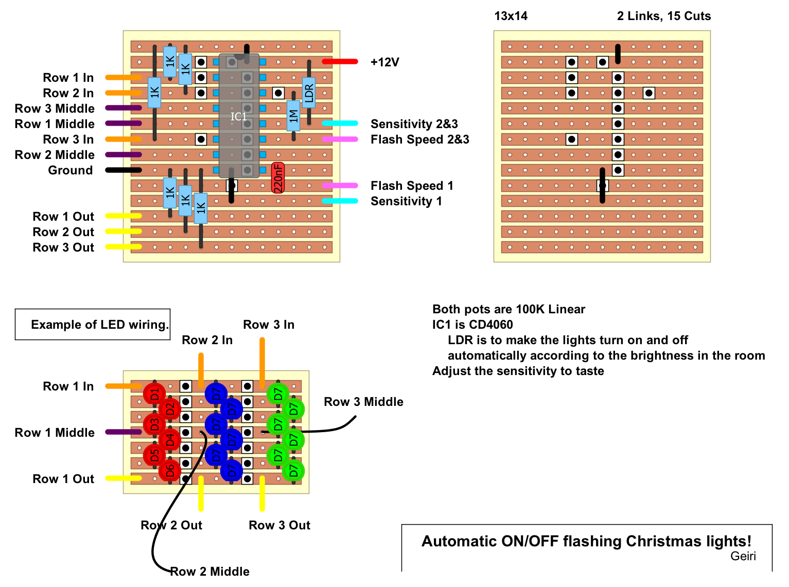 Shematic:
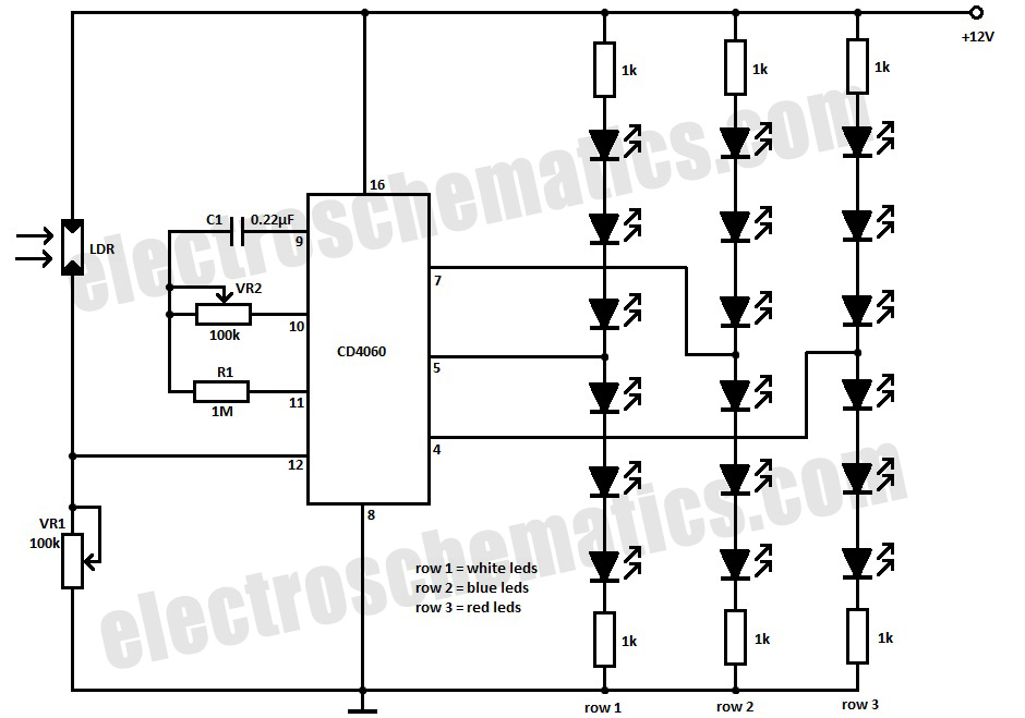
www.pedalprojects.com
www.facebook.com/pedalprojects

