BOYC Orange Distortion

classic Classic list List threaded Threaded
23 messages Options
12
Reply | Threaded
Open this post in threaded view
|

BOYC Orange Distortion

Freppo
This post was updated on .
Verified! :)


/ Fredrik
check out my building blog at www.parasitstudio.se
Reply | Threaded
Open this post in threaded view
|

Re: BOYC Orange Distortion

kavelj22
Nice one. I can see you already have some skills .

I know almost nothing about electronics so it is hard for me to know little things that you said to me.

Anyway, well done!

Oh, would your version fit in to a 1590B housing ?

Reply | Threaded
Open this post in threaded view
|

Re: BOYC Orange Distortion

kavelj22
hi there again...

i don't know maybe it is just me but i can not find connection between R2 and the GND. Also pin 1 of Q1 should have a direct connection to the  +9V, but seems to me that it is missing and few other things that i don't really get...

Maybe you can comment a bit so i can understand!

Thank you very much!
Reply | Threaded
Open this post in threaded view
|

Re: BOYC Orange Distortion

Freppo
This post was updated on .
Thanks :)

Yes, I will fit a 1590B. 21 colums wide is the maximum width for that.

I made this picture that shows the flow of 9 volts (pink), GND (gray) and Vref (green)
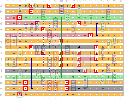

As you can see, R2 connects to ground through the link under the IC
(it's a double link at IC pin 4, I should probably make a note of that on the layout since it's easy to miss).

9 Volts + goes through D3 (for polarity protection, I decided to add it in series insted of between +9v/gnd so it's a bit different from the schematic)

then it goes through R23 which is a 100R resistor (that's another modification by me, R23 in the schematic was the LED resistor or something).
R23 and C15 forms a lowpass-filter on the DC-network which removes and AC ripple coming through from the powersupply that can cause a high pitched squeel.
So anything connected to 9v after the 100R resistor can be considered a direct connection to 9v (only filtered).

The green area is Vref, made up of the resistors R22 (goes to 9v) and R21 (goes to ground) that forms a voltage divider and gived you around 4,5v.

I hope that helps you. Please just ask if you have any more questions

cheers
/ Fredrik
check out my building blog at www.parasitstudio.se
Reply | Threaded
Open this post in threaded view
|

Re: BOYC Orange Distortion

kavelj22
Thanx, for the explanation now it makes more sense.

Why do we need voltage divider - to operate with transistors ?

Thanx again!
Reply | Threaded
Open this post in threaded view
|

Re: BOYC Orange Distortion

Freppo
I'm not that good at the technical stuff, but Vref (voltage reference) is usually needed to power a IC chip from a single supply.

I built my layout today and it works perfectly :)

cheers
/ Freppo
check out my building blog at www.parasitstudio.se
Reply | Threaded
Open this post in threaded view
|

Re: BOYC Orange Distortion

kavelj22
That's awesome. I just started to build mine yesterday. Got the 1590BB today so  i hope i will finish it in the next few days.

How's the sound and everything. Can you make a video of it ?

Thanx, bye!
Reply | Threaded
Open this post in threaded view
|

Re: BOYC Orange Distortion

kavelj22
hi there...

can someone explain to me from the drawings how to connect the stereo jack on the input...it is confusing for me that the battery (-) is connected to the input of the circuit...??? Or i just dont understand how this works ?

Probably the battery should go between + and ground on the board or the ground means something else here ???
And the input is just input from the guitar jack.

Is that correct ???

Thank you very much for your help!!!
Reply | Threaded
Open this post in threaded view
|

Re: BOYC Orange Distortion

Lazy Swamis
kavelj22 wrote
hi there...

can someone explain to me from the drawings how to connect the stereo jack on the input...it is confusing for me that the battery (-) is connected to the input of the circuit...??? Or i just dont understand how this works ?
The battery ground is connected to the lug of the stereo jack that would normally go to "ring".
In this way the battery is only grounded via the "shaft" of the guitar cable plug while there is a cord inserted into the input.

When the cord is removed it is the same as disconnecting the battery.
Reply | Threaded
Open this post in threaded view
|

Re: BOYC Orange Distortion

kavelj22
But how is the LED working then ? In my case it doesn't work. It is connected to the + on the board with the resistor and the - is connected to the ground of the board in this case and this can not work.

How does the LED get the minus of the battery to work ???

Thanx!
Reply | Threaded
Open this post in threaded view
|

Re: BOYC Orange Distortion

Freppo
Check out the offboard wiring guides:

http://tagboardeffects.blogspot.se/2012/02/offboard-wiring.html
http://www.sabrotone.com/?page_id=3451

They should answer any question you have about the wiring :)

cheers
/ Freppo
check out my building blog at www.parasitstudio.se
Reply | Threaded
Open this post in threaded view
|

Re: BOYC Orange Distortion

kavelj22
This post was updated on .
Thank you Freppo...i found what the problem was...

But unfortunately the pedal still does not work. How can i test diferent stages of the board ? Is there some way to find out where the problem is ?


Thank you!


Reply | Threaded
Open this post in threaded view
|

Re: BOYC Orange Distortion

kavelj22
Man...now i know why this doesn't work. In my post with my PCB i used OP2604 but you have changed that to some other IC.

I just saw that now...my good i checked everything like 1000 times

Ok, now i have to buy the right IC that you used in your schematics.

Do you think there is a big difference in use of OP2604 or the one that you have used ???

than you very much!
Reply | Threaded
Open this post in threaded view
|

Re: BOYC Orange Distortion

Freppo
Yes, you need a single opamp IC like the TL071 or LM741 ect.
The OP2604 is a dual opamp IC with a different pinout.

I don't think there's a big difference in sound compared to what I've used.
check out my building blog at www.parasitstudio.se
Reply | Threaded
Open this post in threaded view
|

Re: BOYC Orange Distortion

kavelj22
Man...i can not get this thing to work...

I am going through the PCB again

Reply | Threaded
Open this post in threaded view
|

Re: BOYC Orange Distortion

kavelj22
My god i tryed everything but this PCB does not work. I dont know why.

Bye.
Reply | Threaded
Open this post in threaded view
|

Re: BOYC Orange Distortion

kavelj22
I will try with new one...first on the test board now...

But i would be really happy if someone knows how you can test different stages of this PCB coz i would really like to know why it doesn't work.

It makes me go crazy.
Reply | Threaded
Open this post in threaded view
|

Re: BOYC Orange Distortion

induction
Make an audio probe.
Reply | Threaded
Open this post in threaded view
|

Re: BOYC Orange Distortion

kavelj22
This is very strange. i made a bridge between Q1 output to pin 8 on the output and everything is OK. When i put the bridge after C2 everything goes quiet like the C2 capacitor is dead (i never destroyed a capacitor in my life).

Will continue tommorow with replacing the capacitor!

Thanx for the link Nabble!!!

Reply | Threaded
Open this post in threaded view
|

Re: BOYC Orange Distortion

IvIark
Administrator
In reply to this post by Freppo
Nice job matey
12