BYOC Tremolo


|
Been beating my head on this one for 3 days now. It should be a simple circuit but I am not getting it to work. I am to the point now where I am getting maybe 10-20% volume when engaged, but the audio is clean and not tremolo-y. I hear a high pitched oscillation overtop of the audio that moves at the rate dialed in by the rate pot.
I get no audio when probing the strip between the two cuts on the row where Q2 base is. Things I have tried: - Replaced the 5088s with other and with 5089s, replaced 5457s with others and with J201s - Knifing between rows - Gone over placement of all components, jumpers, and cuts multiple times. - Reflowed most solder joints - Checked for stray wire strands where they attach to the board - Noticed that I originally had R8 down a row too far touching ground (bottom row) and I moved it up. It still looks like something is soldered into the bottom row there if you look at the back, but there are no components there, just solder. - verified off board wiring with the one shown on the layout -verified no component legs were touching above the board - swapped the three caps on the right for film caps (those are for the LFO and can be polarized or not) - traced the circuit for continuity with a multimeter, focusing on the area around Q2, but I have done the whole thing at least twice - Replaced R6 - Checked that volume pot is reading as intended - Removed sockets from under C2 and soldered the transistor in directly because it seemed loose before Voltages to ground are: Q1D 8.97v Q1S 5.34v Q1G 4.25v Q2C 8.96v Q2B 0v Q2E 0v Q3D 0v Q3S 0v Q3G 0.15-0.31v Q4C 3.8-4.1v Q4B 0.54v Q4E 0v Probing reveals some curious things. I get voltages up to the + end of C2 but not the - end of C2. I get audio up to the collector and base of Q2 but not the emitter. Note: I do get voltage at the collector of Q2 but not the base or emitter (seems odd that I get audio but not voltage on the base). However, if I disconnect the ground wire from the board, I DO get voltages from all three legs of Q2. (Although not what they should be). It sure seems like that row is grounding out. I assume my 5457s are genuine because I have used them in other layouts with no issue. I have noticed that from where the SW7 wire connects to the board over to the cut there between the two transistors on that row grounds out when the switch is turned off. Not sure if that's to be expected or not. Note that the value for R8 on the schematic and the layout are considerably different. This is a known discrepancy and the layout was verified after it was changed to 180R. This is also discussed and accepted on the BYOC forum itself. For R8 and R6 I didn't have resistors so I made equivalent values by soldering two in series, which should work from what I understand, but it will be obvious that something different is going on there with my photos. First time posting photos here, so let me know if they need to be bigger or anything... 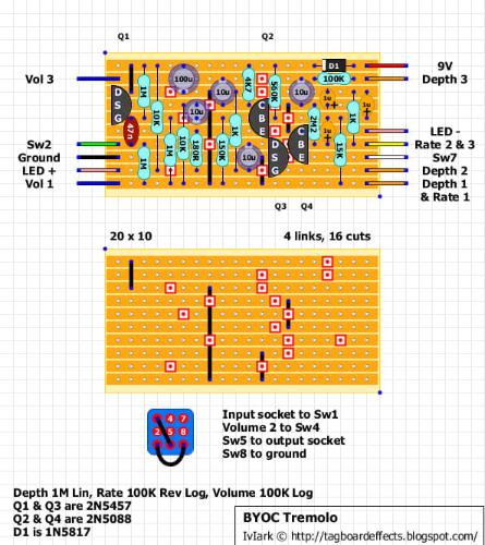 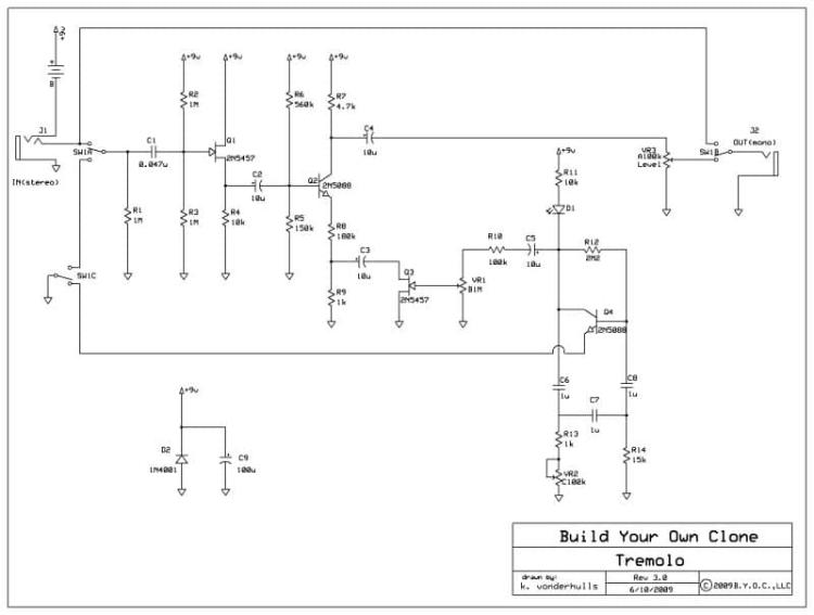 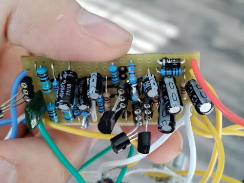 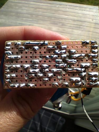 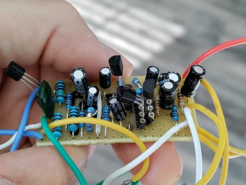 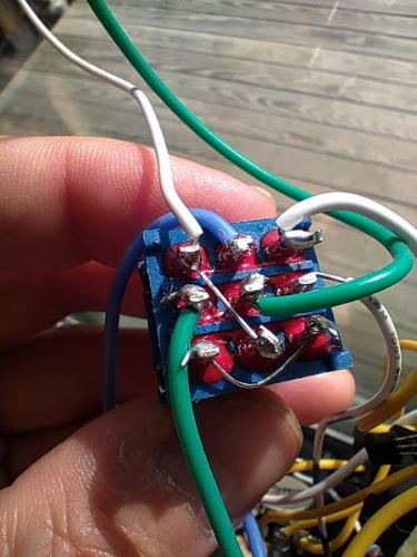
|
«
Return to Debugging
|
1 view|%1 views
| Free forum by Nabble | Edit this page |