Barcus Berry p10 matching preamp
|
This looks like an interestingly simple circuit. In the vein of many one knob boosts. I am working on trying to breadboard this out but it's not working out. If anyone can put this in a vero layout I would be so grateful! Thanks in advance.
Aaron 
|
|
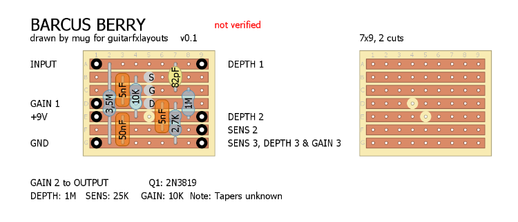
I think this should be it - without the Low Imp. output.
Note that pot tapers are not mentioned in the schematic - I'm not pro enough to give suggestions I'm afraid... 5 and 50 nF are quite unusual values - I suppose 4.7 and 47nF should be ok. Have fun! 
|
|
Wow! You rock! So quick and I can't wait to put something together this weekend for this. I think the original has the sensitivity and depth as internal trimmers so I may try to figure that out. Thanks so much!
Aaron |
|
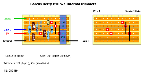
Ok so I took a crack at moving the depth and sensitivity controls to internal trimmers. This is my first time ever using this program so I'm learning as I go. Any pointers to streamline things are definitely appreciated. I am going to try to verify this in the next couple days. Thank you.

|
|
Administrator
|
From a quick glance, looks like you need to swap Drain and Source and swap gain 1 with gain 3
|
|
Thank you. I was wondering about that. In my build experience it seems that lug 1 is usually grounded. I assume it would be the same for the depth and sensitivity controls? I wasn't sure about how to tell source from drain on the schematic. How do you tell?
Aaron |
|
Also, it's hard to tell in the schematic but wouldn't it make sense for those caps to be mF not nF? Those are usually the electrolytics in those places, right? It doesn't say they are polarized but thats all I have in those values so I'll try them. I understand the 50mF from power to ground but which orientation for the 5mF caps? Or maybe those are 5nF?
Aaron |
|
Administrator
|
Lug 1 is not necessarily always grounded depending on the application, but for that type of volume control it pretty much always will be. Schematics often do not label pot lugs but in this case I would first assume that lug 1 is grounded for each pot
Yeah looks like you’re right about the cap values. To determine the orientation of a polarized cap, you will look at the voltages where you are connecting the cap. The + will connect to the higher positive voltage In both cases here, the higher positive voltage will be present where the cap connects to the JFET. So connect the + sides of the caps to the JFET here and the - will go to the pots The JFET symbol on the schematic is usually one of 2 symbols. One symbol shows the Gate in the center like on this schematic. When the gate is shown in the center, it suggests that the drain and source are actually interchangeable for that JFET. You might not always trust this though, someone may use the wrong symbol. You may also see a JFET symbol where the gate is not in the middle, but pointing towards one of the outer legs. In this case the gate will always be pointing at the source The direction of the arrow on the symbol will tell you if it is an N channel or P channel device. The symbol will sometimes be shown in a circle to indicate a discrete device, or shown with no circle to indicate it is part of an IC. People often use the wrong symbol, but at least if the symbol is displayed in its normal orientation it will be DSG from top to bottom |
|
Ok. So I breadboarded this circuit out and something is off. I get a signal coming through but it is slightly less than unity gain. I've also tried a bigger gain pot but that didn't change anything. I've tried 5mF and 5nF as capacitors and it didn't seem to make a difference.
The circuit to the right of the Q1 seems straight forward but something about that area around the depth pot is odd. It looks to me like a 1M from Q1 to lug 2 of the 3.5M depth pot but those values seem unusual. Why is the 1M pot not using a lug 2? Aaron |
|
Administrator
|
This post was updated on .
It actually appears to be a 3.5M pot and 1M resistor the way it is labeled.
It looks like lug 2 of the Depth pot should connect to the JFET gate via the 1M resistor The 82pf input capacitor should cut quite a bit of bass frequencies, it appears that the depth pot essentially bypasses this capacitor to allow more bass frequencies (with a 1M resistor between your guitar and the gate at max depth). At minimum depth your guitar is going through the 82pf cap and you have the 3.5M ohms to ground at the input and the 1M resistor to ground at the gate That setup is kinda odd. If you don’t need the depth control you could just forget about the pot and use an input cap with a larger value (maybe something like 10n-100n would be a starting point) and a resistor from the gate to ground (maybe like 1M) That’s like a semi educated guess on those values so it may need adjustment If you want to be able to attenuate bass frequencies but you don’t want to deal with the funky depth pot here, you could do a simple input cap blend like you see on the Easy Face or DAM Red Rooster |
|
This post was updated on .
So I should be able to remove the depth control section all together?
Maybe just a 1M to ground for possible popping. I have a 100pF in there now but I could bump that up. I also may try a different JFET. I do not have a 2N3819 so I used a BF244a but I also have a 2N5458 I could try. Aaron |
|
Administrator
|
Yes you could omit it by removing the pot and replacing the 82pf cap with a larger value (as I mentioned I would start with maybe 10nf-100nf)
You will need a resistor from the gate to ground. In the stock circuit that varies from 1M ohms at minimum depth to 4.5M ohms at maximum depth. The resistor would fall somewhere in that range to be like the original biasing |
|
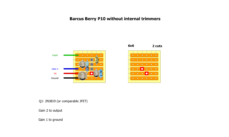
Ok so I got this circuit working (on the breadboard) and have been playing with it. Great little circuit! The sensitivity trimmer didn't really seem necessary to me and I just left it maxed and since I don't have a 3.5M pot handy I decided to make tweaks to leave that out as well.
I made connections to put the input signal through a 1M in parallel with the input cap and ground the gate through a 3.5-4.5M resistor. It still sounded good but didn't sound any different than when I used a 1M pot for depth. Then I removed the 3.5 and 1M resistors and nothing changed. Still sounded great. What gives? Do I not need a ground from that gate then? I have a vero drawn up for this stripped down version as well as a version using an on board pot. I will post those when I get back to the house. Aaron |
«
Return to Unverified Layouts
|
1 view|%1 views
| Free forum by Nabble | Edit this page |


