I put this under requests, but I've been doing some work on reverse engineering this, but I need help from those that have more experience.
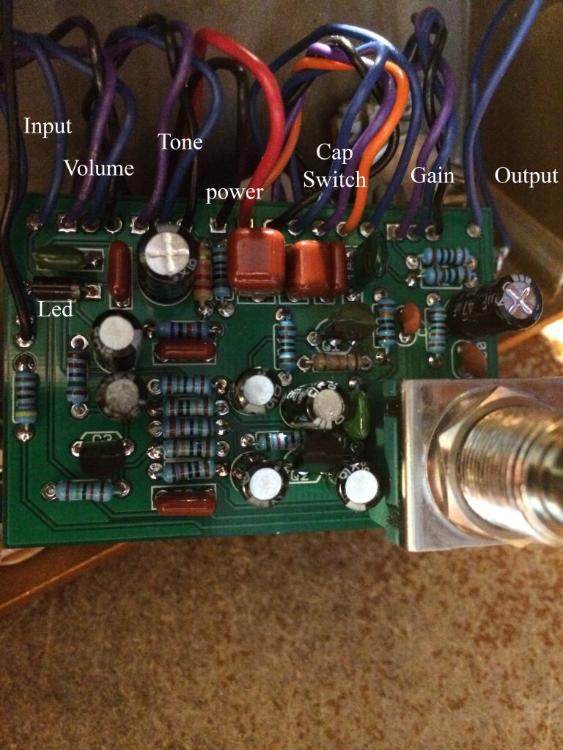
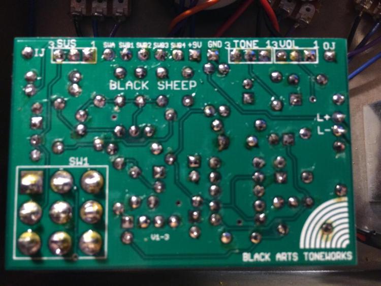
Here are the pics of the board (top and bottom), and i marked all of the caps that i could see as well as the wiring. all the transistors are 2n5089's.
i couldn't see all of the values on the caps, 3 of them on the switch i couldn't see, and the one greenie right next to the switch, which i think is .0022uF. i think the ones on the switch from left to right are the .0022uF greenie, .010uF, .047uF, and 1uF on the end, but since they are their for switching you can sub whatever you want, and we could even make it a 6 way with even more options.


Overlay of top and bottom of board.

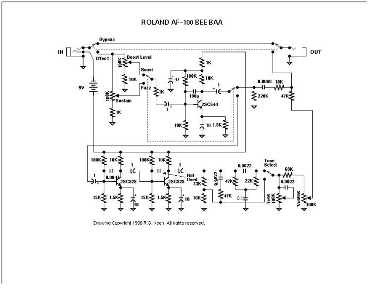
Beebaa schematic

What I've figured out is the input cap is switchable, the 1uF after the sustain pot, in the same fashion as the Black Forest. It looks like the 1k is replaced with a 470pF. The 100pf from b-c is now 330pf at q1, while the others are now 10nF, including the cap labeled not used. There's a 220nF off of volume 1. The boost pot and 10k to ground are gone, as is the 220k, 6.8nF, 10k network to output, as well as the 47k & 68k around the volume pot, and the 2.2nf, 47k network for the tone switch, which is removed.
Need help modifying the schematic so I can make a layout. When I had the actual effect I still found it a little thin, and wasn't happy with the tonestack, but I want to get a working schematic that I can work off of.