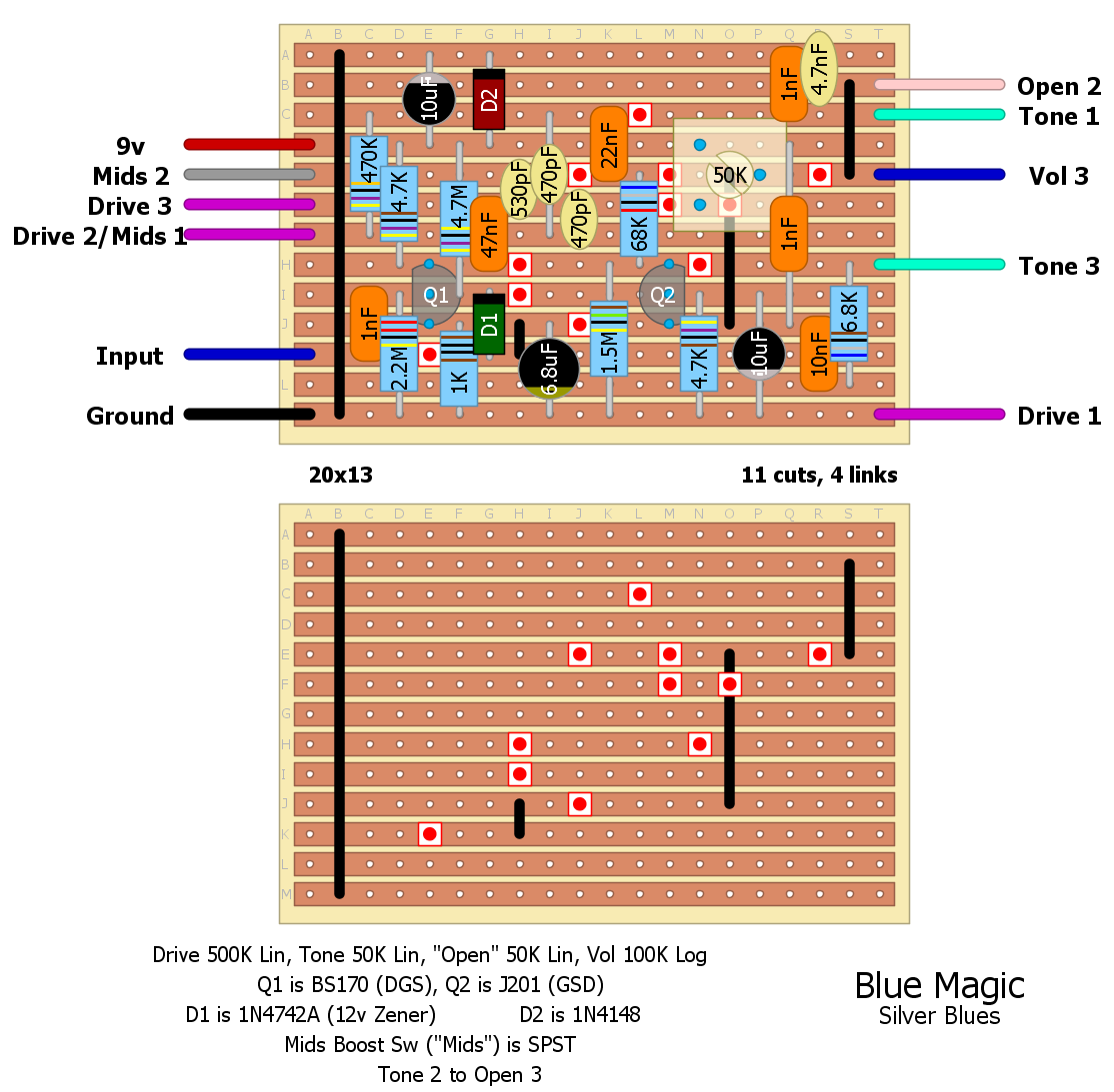
Have a check to make sure everything is in order around the "Mids Boost" switch area, that was a bit confusing to lay out.
The info sheet goes on about switching R11, so I made it a pot instead of finagling with switches. I note 50K on the layout, but if you like you can put a 75K resistor across the pot and make it 30K total, to be closer in range to the original. I'd forego the 4148 parallel polarity protection diode, but I put it in the layout just for verbatim's sake.
Info sheet also says to experiment with coupling caps and bypass caps, as well as C12 (the 4.7n to ground), which is good advice. Have fun!
EDIT Made a little mistake, layout corrected.
Through all the worry and pain we move on