This is a bit of a long one.
A friend of mine got the idea to build his own tape delay for his music. What he lacks in knowledge he more than makes up for in enthusiasm, so he recruited me to help decode all the electro wizardry....all via Facebook. He did all the work in his house while I sat in mine with a bottle of red, my laptop and a PS4. I suppose this is my first "remote" build haha.
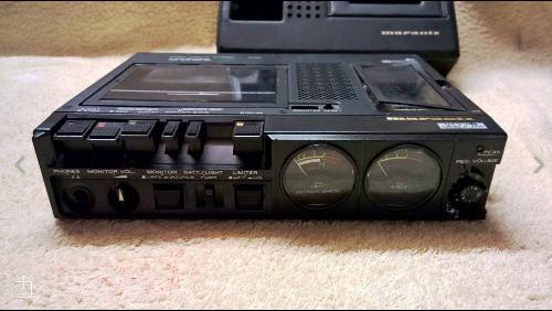
He came across the one time popular Boscorelli circuit when researching and also discovered that some old Marantz tape decks seem popular choices for this. But jesus they go for some price now on eBay! I convinced him to buy a fixer upper one at £54 and it came like this...
Marantz CP-430
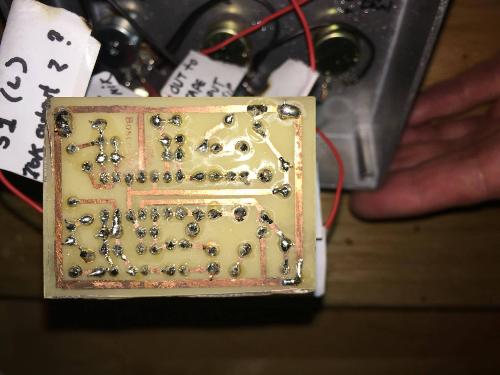
He etched (first time etching) the PCB from the Boscorelli manual and it came out great! I had made up a vero of it as well, just in case. But in the end it wasn't needed. The etch worked fine.
His first etch
Comparing component placement

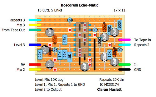
Here's the vero if anyone's interested. I used standing resistors because 1. the PCB does and 2. you'll find out later.

Currently not verified
So he wired it all into an enclosure and hooked up all the ins/outs from the marantz and tried it. Perfect! The mixer worked exactly as advertised. Feedback pot going all the way to oscillation, wet level, overall volume just fine. But...fixed delay time. And it was fast!
Doing some reading suggested the common was to vary motor speed was with an LM317 variable regulator between V+ and the motor. But, these Marantz units have a pitch control pot which slightly speeds up/slows down the tape speed to allow the user to fine adjust playback to maintain correct pitch (tape stretches and changes with heat/time). So I had a look at the schematic to see what could be done about taking advantage of this to slow the tape down even more and get a longer delay time.
The Pitch Control Schematic
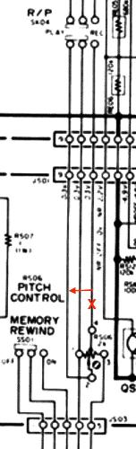
As you can see, the pitch pot has 4 lugs. Looking at the top jumper, the Play/Rec switch actually uses 2 different outputs from the pot. Play uses lug 2 which can be swept through the total pot resistance i.e. allowing the user to vary the speed during playback. But Rec takes its output from lug 4, which is tapped midway through the pot (2K) at exactly 1K. So pitch (motor speed) cannot be varied as its recording for obvious reasons. Well....thats no good for us because the tape deck must be in record for use as a delay.
Pitch Control PCB
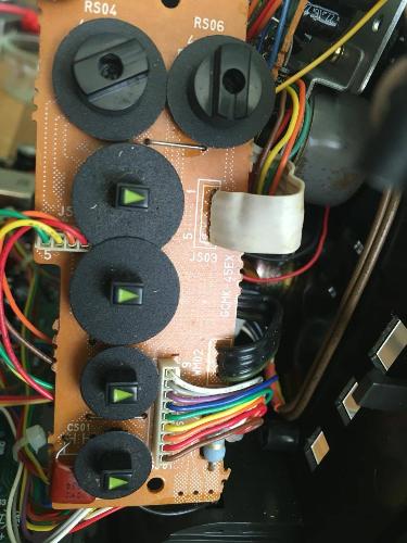
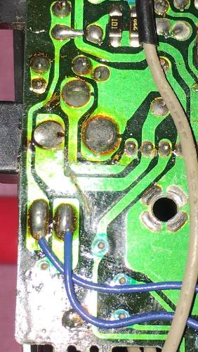
So we cut wire 7 from the top (on the schematic. Bottom on PCB) jumper and spliced it into jumper 9 (lug 2 of Pitch pot). Now we can vary tape speed while recording!!!
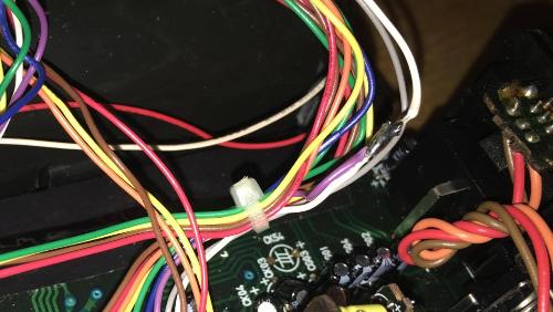
The Splice
So that solves one problem. Now the next...how to actually get it slower than the full travel of the pot, which is subtle at best.
The bottom jumper in the schematic shown connects this board to the motor regulator which spits out different voltages to the motor for play, fast forward, rewind etc. I asked him to measure the pitch pot between lugs 1 and 2 and to note how resistance changes relative to tape speed. We discovered that higher resistance = slower speed.
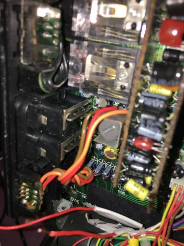
Replacing the pot would have been the easiest way but it would have presented a few silly problems. The knobs on the original one are screw fit...and massive. He wanted to keep the aesthetic of the original device, and function wise, a larger pot would have lowered the resolution for fine tuning the speed. So we looked at how we could keep this pot in place but add another in series, like a coarse pot AND a fine pot...and a finer pot too haha (thats the function of the other pot in the pic. So we located the wire coming from the motor (wire 4 on the schematic bottom jumper) to lug 1 of the pitch pot, snipped it and put a 50K pot in series...lug 1 from the motor side, lug 2 to the pitch side.
The wire was in a ribbon...
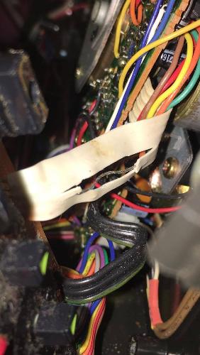
...and with the new pot added
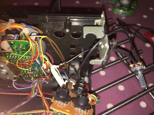
Now we're getting there! The motor slowed right down and stopped just over half way through the sweep. So we set the pitch pot to its lowest speed and tested a few resistor values in parallel with the new pot to find a value that slowed down the motor to a point just before stalling. I think we ended up with a total series resistance of 24ish K. And the beauty of this is that fully CCW it's like the new pot isn't even there so we have a much better resolution than simply replacing the existing pot with a bigger value.
Last few jobs. We now needed to power the mixer circuit with 9V but the Marantz with 4.5V We located the DC socket on the tape deck, cut the V+ trace to the tape circuitry, ran a wire from the socket V+ to the mixer, another from V+ to a 7805 1A regulator and the output of the regulator to the circuit side of the trace cut.
DC Trace cut
Perfect! Both the mixer AND the tape deck can now be powered off the same PSU and using the existing DC socket.
Then we located the inside of the phono sockets and wired the mixers tape send/returns direct to them internally. No more phono/RCA cables!
Phono RCA Internals
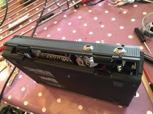
2 jobs left. Find somewhere to cram all this new circuitry, In/out jacks, LED pots etc. Well, this was powered off 3 C cell batteries so the battery compartment was pretty big. In it all went!
Battery Compartment
...screwed it all together
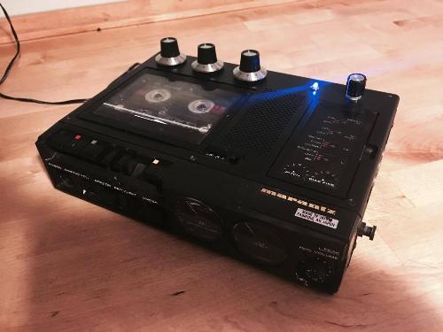
and done!
From left to right...Repeats, Mix, Volume, Time (our new speed pot).
We roughly worked out that we are getting a delay time of about 400ms at MAX. The record head and play head are simply too close to each other to get any longer out of it. We also discovered that the repeats at MAX are darker than at MIN. Must be a product of the way tape records. But it actually helps with tape noise!
Another thing we haven't got round to yet is to add a HPF. Some testing suggested that low freq content may push it into oscillation sooner than you would like. But as he just finished it he needs more time to decide on what needs addressed.
Here's a quick demo he fired up on youtube using his voice and a Moog Sub 37. He's currently recording new stuff with his side project Wake America and he intends on using this delay somewhere. I'll post a link when something comes out.
Personally I think it sounds great. Proper LoFi, gritty, messy and best of all...DIY. Hope you all enjoyed. Feel free to ask questions if any. And dammit...dig out the old walkmen and boom boxes and put them to good use


