Breadboarding and modding questions

classic Classic list List threaded Threaded
6 messages Options
Reply | Threaded
Open this post in threaded view
|

Breadboarding and modding questions

toddvirgil
Hey all,

Well, I'm finally taking the full dive into messing around with my own circuits, and I can tell I'm gonna be hooked. I've done a fair amount of reading, but I thought maybe we could open up this topic for "How would you mod it?" to help noob's like myself learn exactly what parts of the circuit are doing.

My first breadboard is the humble electra distortion as seen here:
http://www.freestompboxes.org/viewtopic.php?t=16440


So! my first question:
I can see that the 4k7 and 470R resistors set the gain ratio of the circuit by dividing the 9v, right?
So, what's special about these values? Is there an advantage or disadvantage of using say a 2M and200K? why not use a 100R and a 10R?

Second question: the 2M2 from the collector to the base -- looks like this is a biasing feature -- can someone point me to an article that explains this to us noobs? I'm assuming the value of the resistor here is interactive with the values used for voltage dividing...I found this: http://en.wikipedia.org/wiki/Bipolar_transistor_biasing

Finally: What would you do to improve this circuit? maybe some power protection/filtering? What's your favorite method? Obviously a gain control and a tone stack... any favorite methods on each of those?

Thanks in advance for any help guys!
Reply | Threaded
Open this post in threaded view
|

Re: Breadboarding and modding questions

induction
First question: You are correct that the 4k7 and 470R resistors set the gain, and could be replaced by other resistors with the same ratio. The difference will be the quiescent current, the amount of current that flows with no applied signal. (The same goes for the bias resistor network).  For a given circuit topology, you can choose the voltage gain and quiescent current for yourself, but the value you choose is a design decision, so it's really up to you. There may be several competing factors that affect your decision, including the optimal operating point of the transistor, and whether you will be using a battery. (High quiescent current drains batteries. Remember that this current flows even when the pedal is bypassed.) For more details, read this.

Second question: the 2M2 arranged this way is known as collector-feedback biasing. It provides thermal stability to the transistor at a low parts count. It is often used for common emitter amplifiers with no emitter resistor (ie maximum gain), to prevent thermal runaway. Read more here. My guess is that this scheme was chosen more for its sonic characteristics than its electronic ones, but I could be wrong.

You can dig pretty deep into this subject, I've just touched the surface here. As for improvements, power filtering is absolutely necessary on these types of circuits, unless you use a battery or a filtered, regulated adapter. Biasing often requires that the positive power rail be connected to the base through a resistor, which means that any ripple in the power supply will be amplified along with the signal. If voltage divider biasing is used, you can filter Vref with a capacitor, and use another resistor to connect Vref to the base. Take this snippet from the LPB-1 as an example:


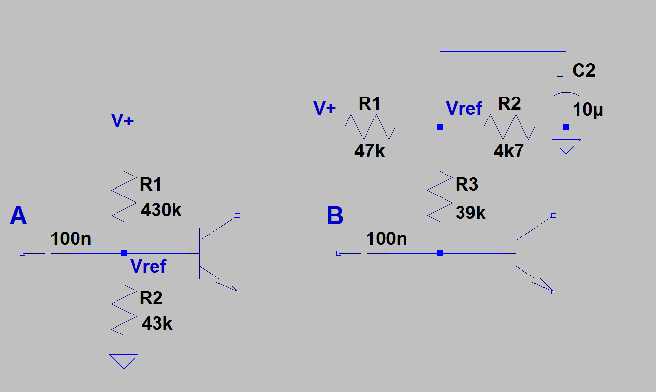
Snippet A on the left is the stock LPB-1 biasing scheme. Snippet B on the right shows how to modify this to filter Vref. C2 provides a path to ground for the ripple at Vref. The 39k resistor provides the same impedance to the signal as the original voltage divider did. Without this resistor, the signal would be dumped to ground or V+ by C2 along with the ripple. These two schemes should sound exactly the same, except that B will have noticeably reduced hum. I applied this strategy to my Orange Squeezer, and the results with an unregulated adapter were dramatic.

The collector-feedback biasing scheme does not allow us to use the same trick, so a battery or regulated adapter is necessary. (There might be another trick that would work here, but I don't know it.) I built a Cot-50, and it was totally unuseable with an unregulated adapter, even with heavy filtering on V+.
Reply | Threaded
Open this post in threaded view
|

Re: Breadboarding and modding questions

toddvirgil
Induction, you are book of knowledge! (Seriously, you should write a book). So much to chew on here... but just want to say thanks for the quick and thorough response. I'm gonna go play, but I'm gonna keep posting questions as I run into them on this thread.

THANK YOU!

T
Reply | Threaded
Open this post in threaded view
|

Re: Breadboarding and modding questions

toddvirgil
In reply to this post by induction
Hey Induction,

So I did some searching around for power filtering and ran across this:

http://www.muzique.com/tech/bipow.htm

Obviously a much higher part count, but it seems it would be an easy chunk to add to a circuit like this without having to mess with the biasing (i.e. might work well on a collector-feedback biased circuit, is that correct?)

Thanks!

T
Reply | Threaded
Open this post in threaded view
|

Re: Breadboarding and modding questions

induction
The top AMZ circuit is a low pass filter (fc = ~16 Hz) followed by a bjt buffer. (Look at the second bjt buffer here and note the similarities.) So instead of buffering a signal, you are buffering a DC voltage. This could be useful for power filtering, and voltage divider biasing, but seems less useful with collector feedback biasing (I could be wrong, though). Buffered Vref is common in some circuits where Vref needs to be rock solid, like compressors. It can also be easily accomplished with an op-amp. In a standard gain stage with a clean power supply, a voltage divider is probably just as good as a regulator.

As for power filtering using these circuits for power filtering, I would call it overkill. It's easier to just use (or build) a regulated adapter. That way you only have to do the filtering and regulation once (inside the adapter). If you build the regulation or power buffering into the pedal, you have to remember that regulation drops voltage, so you will either have to switch to 12V adapters, or use 9V adapters plus a charge pump before the regulator, or, in the case of the bjt power buffer, you'll have to live with the 0.65V drop in the power rail.

I built myself two power bricks with a combination of +/-9V, +12V, and +18V regulated and filtered outputs, powered by laptop PSU's. Then I wired up a bunch of adapter wires and daisy chains. Now I never worry about mains hum anymore.
Reply | Threaded
Open this post in threaded view
|

Re: Breadboarding and modding questions

toddvirgil
Thanks Induction -- I'm mainly thinking about this if I end up selling a pedal like this... in the hopes that it will work well even with less than optimal power supplies. I use a regulated power supply for my own board, so that's not really an issue.

I didn't think about the voltage drop, that's good to know.

Thanks!