|
a veroboard layout already exists for this circuit, but i wanna do a tagboard build instead.
deacy.png ![]() schematic: deacy.jpg haven't built it yet, but i will when all the parts arrive :)
__________________________________
https://www.youtube.com/user/owlexifry __________________________________ |
|
I found this document:
https://docplayer.net/storage/40/21046937/1642951865/uXZJhEYF6Lx02--NrmVG5Q/21046937.pdf Unfortunately, the schematic is not included, just the bill of materials that has some difference in the values with your schematic, especially in the resistors. Maybe because one of the two AC125 is an AC126? In the document we can read something about the heat-sinks for the two AC128 that can get hot during the use. Did you think about it?
I build pedals
|
|
couldn’t load your document..
yes. the ‘true’ deacy amp was based on a ‘PR80 supersonic’ radio, as outlined in this article: https://hackaday.com/2017/05/08/a-queen-mystery-the-legend-of-the-deacy-amp/ this circuit had AC125, AC126, and 2x AC128. this is seen in the schematic for the PR80: ![]() what i have done is drafted a tagboard layout using the ‘greg fryer’ schematic, which i’m assuming was developed to ‘clone’/adapt the circuit from the PR80, using transformers that are actually available(?) (this schematic substitutes x1 AC126 with another AC125, resulting in: 2x AC125, 2x AC128) anyway, it’s the same schematic used for a veroboard layout that’s currently available, i found it here: https://paulinthelab.blogspot.com/2012/06/brian-may-deacy-amplifier-stripboard.html?m=1 yes, i have ordered heatsinks for the 2x AC128 output transistors.
__________________________________
https://www.youtube.com/user/owlexifry __________________________________ |
|
Thanks for the info!
Could you link this kind of heat sink? I'm not sure I understand how it is.
I build pedals
|
|
This post was updated on .
no worries :)
here’s an example https://www.ebay.com.au/itm/Transistor-Heatsinks-TO1-Heat-Sink-NOS-Vintage-5-pieces-/324684537775?mkcid=16&mkevt=1&_trksid=p2349624.m46890.l6249&mkrid=710-127635-2958-0 https://www.ebay.com.au/itm/2-NTE410-Heat-Sink-for-TO1-Type-Package-Lot-of-2-/324326465007?mkcid=16&mkevt=1&_trksid=p2349624.m46890.l6249&mkrid=711-127632-2357-0
__________________________________
https://www.youtube.com/user/owlexifry __________________________________ |
|
Thank you!
I don't know if I'm going to build it, too. Do you think can I use it as a pedal? Replace the speaker with an output jack and go into an amp.
I build pedals
|
|
don't see why not, you'd need probably need to insert an output volume pot.... not sure if it would work that well or sound any good though....
__________________________________
https://www.youtube.com/user/owlexifry __________________________________ |
|
In reply to this post by owlexifry
this has now been built and verified.
works great! only x1 update to the layout required (NFB gremlin) ![]() ![]() updated layout:
__________________________________
https://www.youtube.com/user/owlexifry __________________________________ |
|
evidence:
__________________________________
https://www.youtube.com/user/owlexifry __________________________________ |
|
Great!
Don't this amp have any volume control? Is it possible add any somewhere? What did you use to add distortion in the demo? Thanks.
I build pedals
|
|
there isn’t a volume control per the schematic i’ve been following.
no effects used in the demo. guitar direct into the amp. all tone variations come from the guitar controls. demo starts on bridge humbucker at 2.5, dials up to about 5.5, then switches to cranked (about 8-9) neck pickup. that’s what’s causing the tone changes. it’s a very different playing experience to what i normally do (high gain, metal etc.)
__________________________________
https://www.youtube.com/user/owlexifry __________________________________ |
|
So, a Pre-Gain pot could be cool.
I'm not sure how we could add a Master Volume control. Maybe in the end of the circuit it's not possible. Thanks.
I build pedals
|
|
Pre-gain and master volume should be easy to add. Master volumes don't go at the end of the circuit, they usually go between the preamp and the power amp sections. In this case, I'd try a 2u coupling cap into a MV pot (experiment with the value) right after the 2nd AC125.
|
|
In reply to this post by owlexifry
Hola amigo!, una consulta, ¿por qué añadiste otra resistencia de 560k, debajo de el tranformador de salida? osea hay 2 resistencia y un cable amarillo pasando por debajo, ¿hacia donde va?
|
|
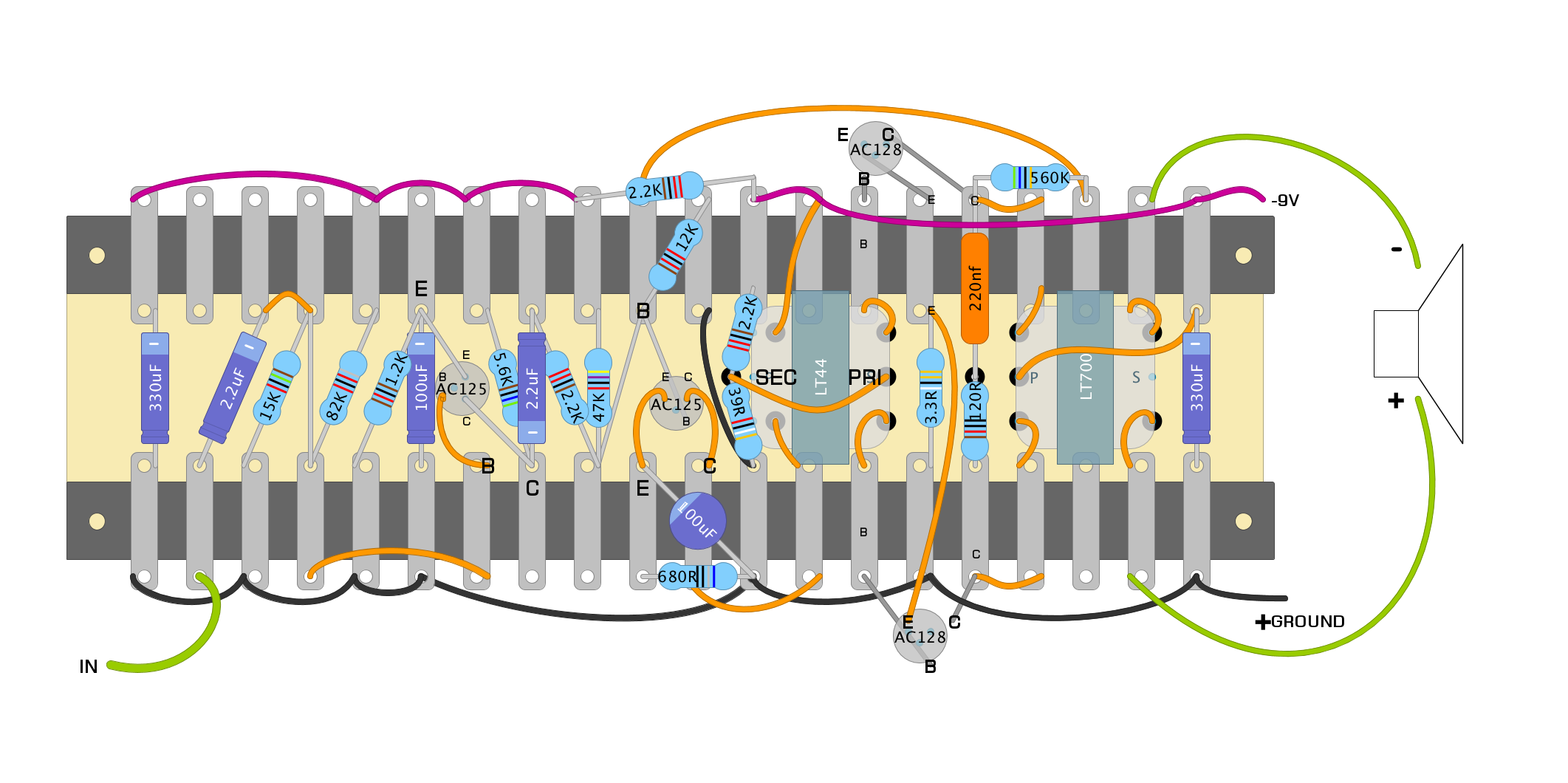
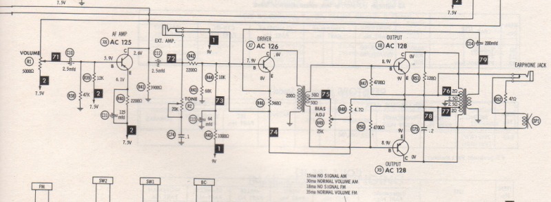
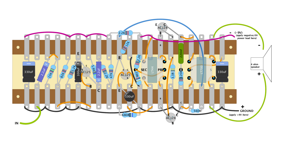
La resistencia de 560K forma parte de un bucle de retroalimentación negativa (NFB). Este NFB envía la señal desde uno de los transistores de salida (Q3/Q4) a la entrada Q2 (base) para estabilizar el circuito. El esquema de "https://paulinthelab.blogspot.com/" indica que este 560K toma la señal NFB de Q3 (colector).
Tras la primera prueba del circuito, se hizo evidente de inmediato que este 560K estaba en el lado incorrecto (transistor incorrecto), ya que causaba retroalimentación positiva (chirrido, oscilación) en lugar de negativa. Por lo tanto, se movió esta resistencia de 560K de Q3 a Q4. Tras esto, el circuito funcionó con normalidad, sin oscilaciones ni chirridos. Por esta razón, se modificó y actualizó el diseño. [the 560K resistor is part of a NFB (negative feedback) loop. this NFB sends signal from one of the output transistors (Q3/Q4) back to Q2 input (base), to stabilize the circuit. the schematic drawn by "https://paulinthelab.blogspot.com/" indicates that this 560K taps the NFB signal from Q3 (collector). after the first / initial testing of the built circuit layout, it was immediately evident that this 560K was on the wrong side (wrong transistor) - as it was causing positive feedback (squealing, oscillation), instead of negative feedback), so this 560K resistor was moved from Q3 to Q4 - after I did this, the circuit was operating normally without oscillation or squealing noise. this is why the layout was changed and updated.]
__________________________________
https://www.youtube.com/user/owlexifry __________________________________ |
| Free forum by Nabble | Edit this page |
