Buffered Bypass..for the new guy :)
|
Howdy folks ,
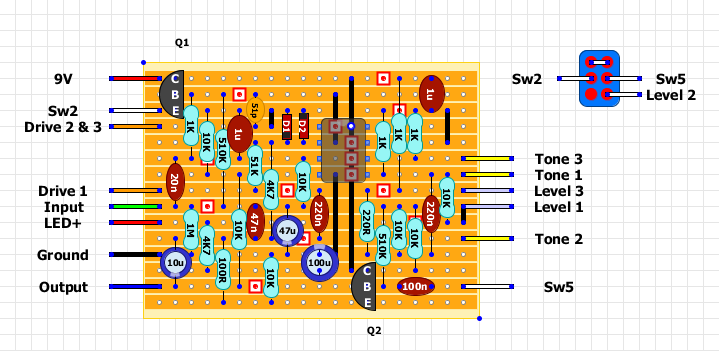
Love this forum , cant get over how much info there is on here !!, although i cant find one bit of info anywhere lol ....was wondering if someone could let me know how to wire the TS808 as buffered bypass ...i have made Marks layout with the buffers in tact but cant figure out how to wire it as a buffered bypass , is there anyone out there who can point me in the right direction ....obv its working as its a verified layout and i have full signal and control , i would just like to wire it up the old way :) Great site guys , you really have excelled !! Cheers again Stoogie |
|
I'm pretty sure you would need a 4PDT switch. Unless you don't mind giving up the LED light. I'd love to see a good answer to this as well...
|
|
Im not to sure on this one ...i was thinking that it wouldnt be too complex ..switching the level feed to the output buffer out and switching a feed/path from the input buffer to the output buffer ....my messy thought was breaking the track at pin 3 of the ic and and switching the feed from there to the output buffer ..and just make and break the level control out of the signal path .....i could be miles off here though !!
Man gimme 1-3 phase 120-400v ill work it out ..but this sometimes boggles me haha thanks for your response mojo hopefully a few heads get on this and i can get some help to figure this out :) |
|
Administrator
|
In reply to this post by Stoogie
The included buffers are the input and output buffers. Buffered bypass would leave those still in circuit but bypass the main amplifying and tone section of the circuit. You can see the bypass circuit quite clearly in this schematic in the bottom half:
http://distortionpedals.org/wp-content/uploads/2012/10/tubescreamer-schematic.jpg So as you can see, adding 5 transistors plus all the peripheral components would add significantly to the size of the board, in fact in may be double the size of the board you just made. That is why all layouts on here are designed with true bypass switching in mind, because stripboard doesn't lend itself as well to complicated switching as a PCB would, limited as you are by fixed rows and untidy links. As I said on the thread last night, I may do a layout for the switching section only so anyone could add it as and when they want to this kind of effect, but I can't say exactly when I will be able to do it. |
|
Yeah i totally understand where your coming from if you were going to make this using the trannys to switch ...cant this be done by mechanical only switching ...bit rough but i was thinking i could bypass the amplifier and the return feed from the level pot and switch in a path to the output buffer ?....would be tring to do this as simplified as possible maybe i am just looking at it from the wrong angle though ...i have been using the technology of the tube screamer(R.G Keen) as a guide do you think this is possible or would i be walking down the wrong path ?
Cheers for your input Mark your a top bloke ...and i done 30 mins of add clicking for ya :) Cheers |
|
Administrator
|
Ha ha, thanks
 You could certainly try that but it could possibly take a bit of experimentation to get it right. If I was going to try it I'd do it like this first and see what happens: 
|
|
Heya mate ,
No worries man , i genuinely do make a point of doing the add clicking as i know how time consuming running a site like this is ....i started a appreciation page/forum for an old breed rally car years ago ..i had to give it up and let other guys take over as it was taking up so much of my time , so i do believe in either donations or now generating money from add's for the guys that run it , take my hat off to you mate ! , As for the switching looks like i wasn't too far off :) thanks for the help i will have a crack at it first light and ill let you know how i get on , and thanks for taking the time to do a layout too :) ....like i said you put a shitload of effort in mate ! I will post up how it goes tomorrow Cheers Mate |
|
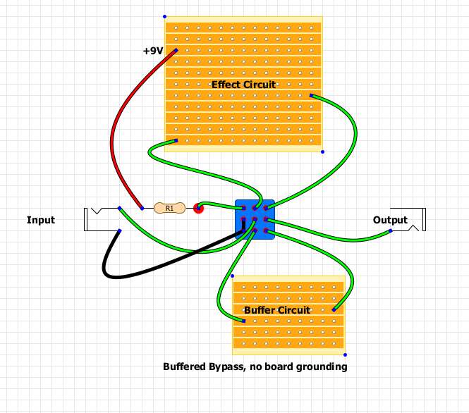
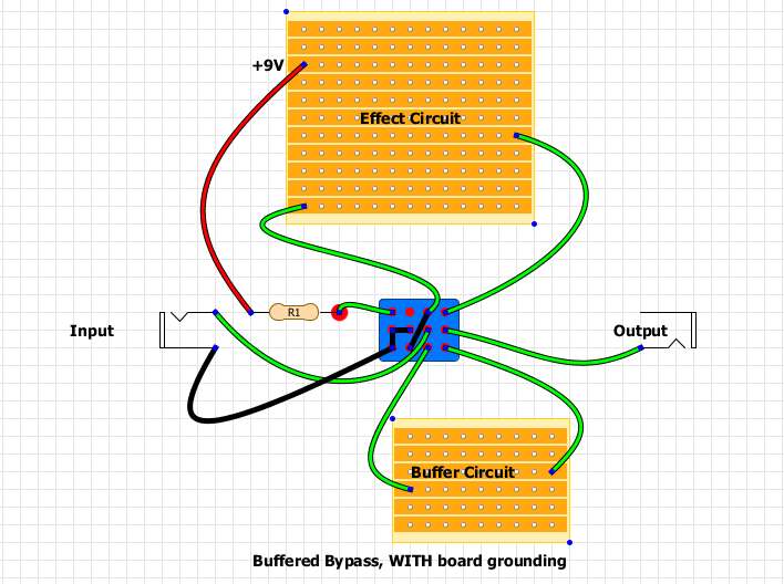
Couldn't you use a simple Cornish buffer on a daughterboard? Here are my two attempts, one with a 3PDT which goes back to the wiring method shown on the Beavis Audio (no grounding of the board input), or two with a 4PDT to put the input grounding back in during bypass:
  |
|
Administrator
|
Yes you could do that, although it is making it complicated meaning you need a 3PDT stomp AND a separate buffer for bypass. The beauty of the Ibanez and Boss type buffered bypass is that you can do it with any cheapo momentary single pole contact and with the buffers already built into the effect.
The way I showed it above effectively does what the flip flops do in the Ibanez original, but with a mechanical switch, although the way you mention would be better for the effects that don't have the input and output buffer as part of the main circuit. |
|
yeah i was thinking the same could be done no problem ..then its ts808..and x buffer ..not the same ..unless of course you made up the in and out buffer section of the ts on a separate vero ...which would be pretty close to original , i just figured the way Mark has shown would be possible i just wanted a second opinion being honest :) ...save me hacking up a perfectly good ts layout and making a twat of it lol
Seems a waste of time to most folks thesedays but i actually dont mind a good buffer and the ibanez/boss buffers werent all bad back in the day ! Cheers for all the input :) |
|
Hey Mark , just to let you know ....not that i ever doubted your way of doing things that it worked first time ...used a 3PDT and retained the led etc , works perfect and the buffer has no tonal effect , be haves like a normal buffered bypass only works with a battery connected etc ,
Would i be mad in thinking the pedal has more drive though ?....dont ask me why and i did jam the pedal as TB but i swear it has more drive ...maybe its just me ? ....could you see any theory as to why im thinking that ?...mulled over the schematic and i cant see why this switching would make any changes when in effect mode ? ...like i say the bypass signal is perfect unity and no tonal changes so all good there but the pedal seems 'better' for this ....who knows maybe i need to turn the space heater off as i think im od'ing on Co2 haha Once again thanks Mark ..top bloke :) , I will try to post more and maybe upload some of my build pics Cheers matey |
|
Administrator
|
Excellent, glad it worked out ok. There's no reason why it should affect the drive. When the effect is on the only thing that is added to the circuit from the way you had it before is an extra wire hanging off Q1 emitter but not connected to anything, and a bit more copper between Level 2 and the input cap of the output buffer. So I think it may be in your head

|
«
Return to Open Chat
|
1 view|%1 views
| Free forum by Nabble | Edit this page |

