N00b alert. I'm building a test box so I can test my circuits before I box them - it's a VERY simple version of the Test Box 2.0 layout, without the sag/probe terminals, etc. Rather than use a stomp switch, tho - I thought I would use a DPDT toggle switch - my local surplus store has buckets of them for $0.50, and they're this one - top picture on right:
R13-448 Toggle SwitchInternal diagram and pin layout on the spec shows this:
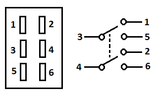
But on the switch itself, it's numbered like so:
1 - - 4
2 - - 5
3 - - 6
I'd like to wire it so that in the 'off' position, the clean signal comes through (bypass) and in the 'on' position, the effect is added. Assuming that the switch internals match the diagram above, would I be able to wire it as follows:
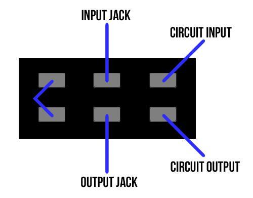
Is this the correct wiring setup? If not, what switch/wiring would be the way to go to accomplish this?
Thanks in advance.

