Building a test rig

classic Classic list List threaded Threaded
5 messages Options
Reply | Threaded
Open this post in threaded view
|

Building a test rig

tjdracz
After using my less than efficient method of debugging circuits, I've decided to build myself a test rig with signal oscillator to do some signal debugging by probing.

Now, I'd like to use this as an oscillator: http://www.aronnelson.com/gallery/main.php?g2_view=core.DownloadItem&g2_itemId=2316&g2_serialNumber=2 - based on RG's project. Seems to be everything I need.
Now I've got couple of questions of how to wire this damn thing up!
I guess I need DC input there, output jack to send signal to amplifier and probe.
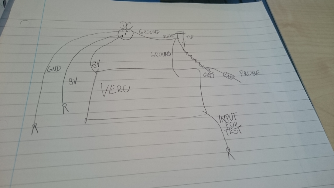
Now, bear with me. From dc jack I wire ground to the jack sleeve and +9V to the vero for oscillator. Also connected to DC jack, two alligator clips for debugging. Red one for +9V and black one for ground. Then yellow alligator clip for input to the tested board connected to generator vero output. Finally the testing probe connected to tip and sleeve of output jack on one end and with alligator clip and capacitor/probe at the other.
Does all of that wiring make sense?
Below is the picture of the wiring (sorry for the quality)


Now, do I need 9V/GND from DC and also GND for probe or will only one do? Also, what happens if I were to debug a -9V board? Do I need a voltage inverter there to make it work with +9V oscillator? And what happens with probe GND connection?

Thanks!
Reply | Threaded
Open this post in threaded view
|

Re: Building a test rig

Frank_NH
Excellent idea building a test rig.  I always "rock before I box" now to make sure everything is OK on the board, as boxing itself is a bit work and it's frustrating to have it all together and then something not work (grrrr  ).

Setting aside the signal generator for a moment, your test rig needs only one ground and I'd wire all grounds to the same point.  Also, make a provision for both battery and a +9V jack - that way, if power filtering on a circuit is an issue you can test it using a battery.

I would also make your audio probe detachable so it's not connected with you have the board connected to the output jack.  What I've done is to simply take the wire that would normally be connected to the board output and attach it to my audio probe.  You can get fancy with this and use a switch to select audio probe or normal output.

I haven't tested any -9V circuits yet, but if I did I'd attach my 9V wire to ground on the board and the ground wire to the -9V input on the board.  I believe that should work.
Reply | Threaded
Open this post in threaded view
|

Re: Building a test rig

Travis
Administrator
True dat ^

Or for the sake of testing you could have an inverter there providing 9v+, 9v-, and 18v. Maybe connect those to a terminal block so you can do the connections solderless
Reply | Threaded
Open this post in threaded view
|

Re: Building a test rig

tjdracz
Cheers guys. I can understand what needs to happen, common ground for everything. Only fear I have is the "don't mix positive and negative ground or you'll die in hell" credo everywhere.
On DIYSB someone mentioned:
"so, it follows, if you have a dc blocking cap at the osc output, and another as the probe input, and the c.u.t. has a ground common with both, it doesn't matter what polarity any of the devices is powered with/by. but I've been wrong before."

So basically common ground for everything and then when needing -9V, just swap the clips from 9V supply? I suppose I could just try that on a breadboard and put a diode to protect from wrong polarity. If it works fine, if it shuts voltage to the ground, then a problem ;)
Reply | Threaded
Open this post in threaded view
|

Re: Building a test rig

tjdracz
http://tagboardeffects.blogspot.co.uk/2012/05/negative-voltage-inverter.html - actually, what do you guys think about using this for the sake of it? Run the pwoer supply ground clip to the ground and have +/-9V (with 9V taken from the top row) switchable by SPDT?
Actually looking at that if the ground is common for pwoer supply and -9V source, the original idea should be fine and my fears for mixing positive and negative were unfounded. Still might be pretty neat to have this switchable and have red clip always being source and black being the ground ;)