CE-2 Problem Please help

classic Classic list List threaded Threaded
15 messages Options
Reply | Threaded
Open this post in threaded view
|

CE-2 Problem Please help

loupy31
Hi I recently finished building the CE-2 , only to find it is not functioning , When I activate to pedal, I get  low level Audio that is very muffled, I have checked the placement of parts, checked soldering and touched up some of the solders joints, I have replaced the IC's as well as the transistors, But every time I test it after I have checked something, I still get the same  muffled audio.

Ant ideas would be great.

Peter
Reply | Threaded
Open this post in threaded view
|

Re: CE-2 Problem Please help

IvIark
Administrator
Sounds like a bad connection somewhere if the components have been swapped with the same results.  Post the voltages for all IC and transistor pins.  That will usually give us the best clue as to where the problem lies.  See how they compare to these working voltages, anything far off from these voltages will give an indication of an area to go over carefully looking for poor soldering, unwanted bridges etc


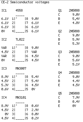
Note that the trimmer will affect some of these voltages so check with that being tweaked too so you can see the upper and lower limits
Reply | Threaded
Open this post in threaded view
|

Re: CE-2 Problem Please help

loupy31
Hi IvIark,
   
 Thankyou for your reply and the voltage chart.

I powered up the unit and checked all the voltages, comparing mine to your chart.

They were all very close, I wont list all of them, but the one reading with the largest difference was Q5 pin C, mine came up with 7.6v, the rest were all within .2v.

Q4 pins B & E , fluctuated  between 3.9 and 5.2 (approx.) Not sure why.

IC MN3007, pin 3 required adjusting of the trimmer.

If you still want the complete list of voltages, I can post it.

I have gone over the soldering, Correct components in there correct places, still cant find anything.

One thing I will mention I am using 1N914 diodes instead of 1S1588.

Regards Peter

Reply | Threaded
Open this post in threaded view
|

Re: CE-2 Problem Please help

loupy31
My Voltage readings

IC1 4558

1    6.13v
2    6.13v
3    6.13v
4    0v
5    6.13v
6    6.13v
7    6.13v
8    9.35v


IC2 TL022

1    varies
2    4.68v
3    varies
4    0v
5    4.67v
6    4.67v
7    varies
8    9.35

IC3 MN3007

1    9.22v
2    4.8v
3    5.31v
4    0.62v
5    0v
6    4.78v
7    5.3v
8    5.3v

IC4 MN3101

1    9.22v
2    4.7v
3    0v
4    4.78v
5    0.36v
6    8.1v
7    2.9v
8    0.62v

All Q's are 2N5088

Q1 c, 9.3v b, 5.26v e 4.88v

Q2 c, 9.3v b, 5.86v e, 5.33v

Q3 c, 9.3v b, 5.43v e, 5.01v

Q4 c, 9.25v b, 4.5 ish varies e, 4.5 ish varies

Q5 c, 7.6v b, 0.4v e, 0v


My power supplies is 9.35v

Peter
Reply | Threaded
Open this post in threaded view
|

Re: CE-2 Problem Please help

IvIark
Administrator
Well your voltages look pretty much exactly what you want to see which makes me think the problem is likely to be something simple like a bad connection somewhere, maybe just a bad joint, but it could of course be a faulty IC or something that just isn't behaving like it should even if the voltages appear good due to the surrounding components.

This is one of those where the quickest way to diagnose the problem is going to be using an audio probe to trace through the signal path to see exactly where the sound is dropping off so you know the area to concentrate on.  Have you used one before?
Reply | Threaded
Open this post in threaded view
|

Re: CE-2 Problem Please help

loupy31
No I haven't used an audio probe, but I don't have a prob. picking things up quickly .
Do I build one or do I need to buy one.

Peter
Reply | Threaded
Open this post in threaded view
|

Re: CE-2 Problem Please help

IvIark
Administrator
You can make one with a spare guitar cable as per this page

http://www.diystompboxes.com/pedals/debug.html

So you plug your guitar into the pedal input and then probe the circuit from input to output following the signal path in the schematic.  At the beginning of the circuit you should get the dry sound and then you carry on through the circuit until you get to the point that the signal drops out.  That will show you clearly where a problem originates and so make it clear what components may need swapping and/or connections/soldering checked.

If you refer to the schematic posted at Electrosmash:

http://www.electrosmash.com/boss-ce-2-analysis

Start at the input and move your way through the circuit from input buffer > Pre-emphasis filter > Anti aliasing filter > MN3007 > Recnstruction filter > De-emphasis filter and see what point you lose it.
Reply | Threaded
Open this post in threaded view
|

Re: CE-2 Problem Please help

motterpaul
That is a large circuit. I have found that when I have a problem it ends up being a small misalignment in components.

You can look at a build 100 times and not see the mistake. The audio probe helps you zone in on the problem.

But also - I think a fresh pair of eyes is a great help, and that means posting pictures of the build here. That is what I plan to do in the future - after spending days troubleshooting one project where I finally found I had misplaced a cap.

Other things you can do quickly - take DMM and measure all resistors. They say you cannot accurately measure one that is mounted in a circuit, but if the circuit is powered down you can get a pretty good idea if you have a wrong value. I just found a circuit where I had a 470R instead of a 4.7k - and it was very easy to find with the DMM.

also - try pulling on all components (not too hard) enough to see if they are not tightly soldered. If you have a cold solder joint it should pop out if you tug on it.

Also - test for (unwanted) continuity row to row on the back and between cuts.
Reply | Threaded
Open this post in threaded view
|

Re: CE-2 Problem Please help

loupy31
Hi Guys,

Ok I built the Audio probe, and got it working ok.

This is my first finding, from the input through to the junction of C2, C3 and R4 the Signal is fine, past that point on the other side C3, only the high frequency is allowed through, on the other side of R4 the signal drops to less than half what it was before that point, the reduced signal remains at that level for most of the circuit till it gets to IC1B (output stage).
When I probe pin 7 on the 4558, the signal is heavily reduced and muffled as I commented in my initial post.

Any thoughts please, I feel like I am making some progress, if only a little.

Regards Peter
Reply | Threaded
Open this post in threaded view
|

Re: CE-2 Problem Please help

IvIark
Administrator
Well it certainly sounds like a problem with that IC.  Is the soldering all good and the cuts clean between pins?  Have you soldered directly or socketed it?
Reply | Threaded
Open this post in threaded view
|

Re: CE-2 Problem Please help

loupy31
I have used a socket, soldering and cuts all look good< I have swapped out IC with same results, I will recheck all components around it as well, The audio dropping after Q1  is this a normal thing, or should the signal level be the same through out the circuit?

Peter
Reply | Threaded
Open this post in threaded view
|

Re: CE-2 Problem Please help

IvIark
Administrator
No it isn't normal, that's just a buffer so input and output should sound very similar, but the signal could be being dragged down by the IC which follows it.  If you've swapped it it sounds unlikely that it's faulty, but use the resistance tested on your meter to check that you're getting no resistance between the solder and the springs of the socket, just in case you have a bad connection in there anywhere.
Reply | Threaded
Open this post in threaded view
|

Re: CE-2 Problem Please help

loupy31
This post was updated on .
Hi IvIark,
                First let me say thanks for the time you have put in with this problem I am having.

              Ok, checked for resistance in all sockets, tried 3 other chips (IC1), replaced all the 2N5088,
and several of the caps, Unfortunately the prob. remains,

    Peter
Reply | Threaded
Open this post in threaded view
|

Re: CE-2 Problem Please help

loupy31
Hi IvIark,

This morning I went over all the components, just to triple check they were all the right values and in the right position on the board.................... To my surprise the 2  100pf caps, were in fact 100nf.
in my defense  they looked Identical, After replacing them for the correct value, the unit came to life, with the exception of some noise most likely an earth problem, which should be easy to fix.

Once again thanks for your help, your info. has sharpened up my fault finding skills.

Many Thanks

Peter
Reply | Threaded
Open this post in threaded view
|

Re: CE-2 Problem Please help

IvIark
Administrator
Nice one Peter, glad you got it sorted