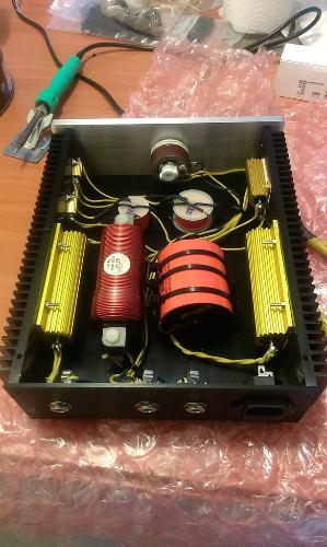
I´ve finished this amp attenuator project that sounds pretty nice.

It´s mainly a "bedroom" atennuator, in fact the way is configurated, it sounds better as you go down in volume, but at 0 attenuation, (rheostate open all the way), you get like 10db of attenuation to start with, what is enough for playing in a band situation with a 100w cranked loud beast.
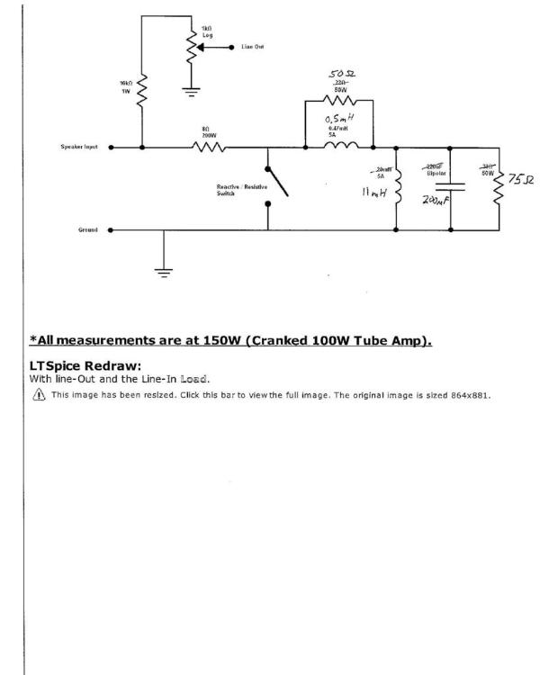
It works mixing resistive, capacitive, and inductive elements into to the circuit to simulate the impedance curve of an average 12" speaker with that typical peak at 100hz, a valley and then go rising from about 1khz.
Then isolates the rlc load with a resistor and then to a rheostat.
The circuit is very similar to the following, (mine is for a 16ohms load), but this one has a line out control, so you can do things like recording with a computer audio interface:

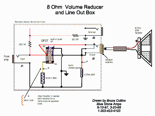
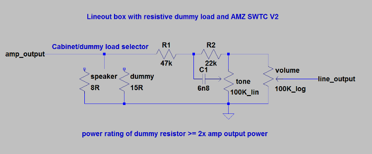
There are other examples of placing a line out:


As you can see, the voltage dividers are different in value, so I´d like to know what to choose or how can I calculate this.
May be finding out the impedance input of my audio interface would help...
Cheers, Gilberto.