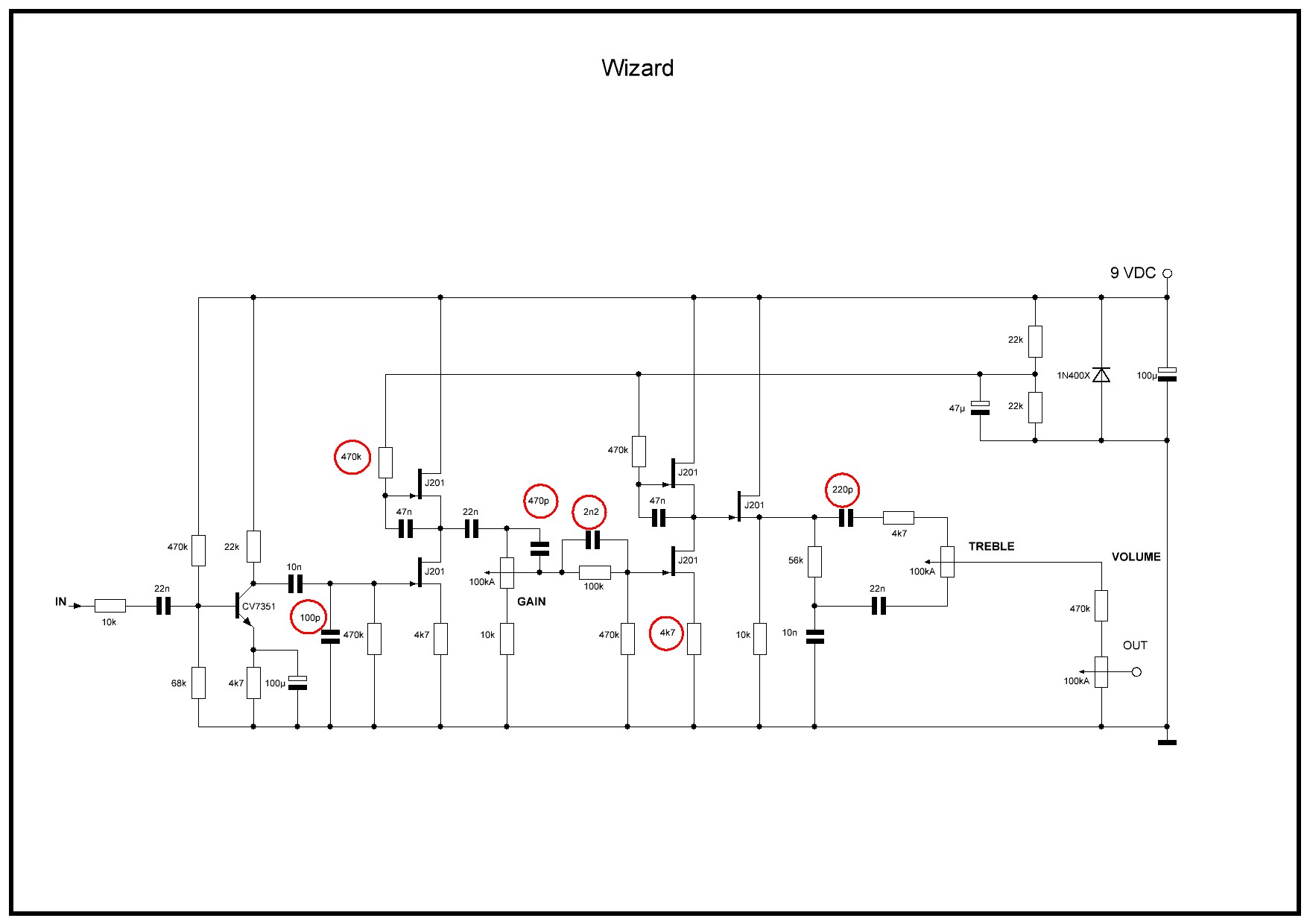
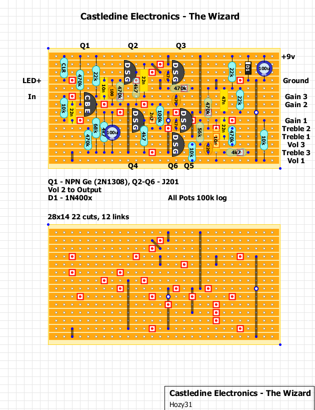
Castledine Electronics - The Wizard
12


12
|
I know this one hasn't been traced yet but I'm keeping a close eye on it. It's simple so it's doable once there's a schematic. I like the sound of it. Check the clips that have been linked in the thread.
http://freestompboxes.org/viewtopic.php?f=7&t=21740
www.pedalprojects.com
www.facebook.com/pedalprojects |
|
The schematic has been out a while now. I really want to see this as well. Until I can get a diylc for android to work I'm not much help.
 sorry for such a big ass pic. When I tried resize it didn't show up in any way that was useable. sorry for such a big ass pic. When I tried resize it didn't show up in any way that was useable.
Here's the thread and post from fsb that I grabbed that from http://www.freestompboxes.org/viewtopic.php?f=7&t=21740&hilit=Iommi+boost&start=20#p263702 |
|
Administrator
|
Already on this one. Gonna get finished during my next few study breaks.
|
Re: Castledine Electronics - The Wizard
|
Nice! Keeping an eye on this thread.
|
|
This post was updated on .
Rustled up a layout but its quite big. Let me know if you spot any mistakes. Not sure i have the Treble 2 and Vol 3 connection correct.
Updated: Found a couple of errors, hopefully all good now. Built first version and it didn't work, found errors and rectified and built, so this version below is now verified! Since there was room I added a current limiting resistor (CLR) for the LED. LED- to bypass switch. 
"Red velvet lines the black box"
|
|
THANK YOU, I'm gonna look it over and maybe build one tonight to check it.
HELL YES!!!!! Supernaut here I come |
|
In reply to this post by Hozy31
I see that the 68k should be base to ground but otherwise its lookin good, thanks
|
|
Thanks for the heads up. I managed to fit it in by moving a few things. Also spotted a couple of missed trace cuts.
"Red velvet lines the black box"
|
|
I appreciate it. I put the 68k in the hole with the 470k. Thanks man I'll biild it this weekend and let you know. The treble wiper to 470k to volume 3 looks right btw
|
|
Administrator
|
just put my layout on the main page. it's a little narrower & little longer, a few less cuts & jumpers. i went over it a few times, and should be good to go.
|
|
In reply to this post by Dex3887
I built the layout above and its not working. Found the culprit and will update once i have verified it, So hold on your build just now.
"Red velvet lines the black box"
|
|
In reply to this post by Dex3887
Dex3887, the new version above is now verified!
"Red velvet lines the black box"
|
Re: Castledine Electronics - The Wizard
|
In reply to this post by Hozy31
Must the jfets be biased?
|
Re: Castledine Electronics - The Wizard
|
The first four JFETs are set up as muamps (or SRRPs, never quite sure) so the "upper" JFET has drain to +9v, so - no, they don't need biasing. The last JFET is a single stage, but wired as a buffer, also with drain to +9v, also doesn't need biasing. The Ge input stage (rangemaster boost) might well need a tweak to the bias depending on the transistor used.
|
Re: Castledine Electronics - The Wizard
|
Can someone please tell me how can i tell the difference between circuits that need biasing and those that don't?
|
|
This post was updated on .
Added CLR since there was room. Edit: ignore comment on Gain pot it was meant for another thread

"Red velvet lines the black box"
|
Re: Castledine Electronics - The Wizard
|
In reply to this post by GrooveChampion
Mainly from experience of looking at dozens of different designs and being familiar with the various bias arrangements for different types of transistors. In general, JFETs vary considerably in their spec so a single JFET with one resistor each on its drain (to +9v), source and gate (both to ground, or gate to 1/2V) will require biasing, usually via the drain resistor. JFET buffers, mu-amps and SRRP arrangements have no drain resistor and do not usually need biasing (JFET buffers usually require a gate-to-1/2v connection, but in the Sabbra cadabra, the buffer gate is DC-coupled to the output of a mu-amp, which has its own 1/2V supply that it shares with the buffer). For BJT devices, a simple (but not very scientific) rule of thumb is that the more resistors associated with each stage, the less likely you are to need to bias: e.g. the fuzzface has only two resistors per stage: The operating point is therefore heavily dependent on the particular semiconductors you choose; The Big Muff, by contrast, has four resistors per BJT, meaning virtually any transistor type or hfe can be used with minimal variation in the collector voltage. Transistor stages with feedback between C-B are often used to reduce the need to bias/choose particular transistor spec. Any design featuring Ge devices (e.g. mid-60 fuzzes) are often primitive from a biasing pov and may well need a tweak. |
|
Have some germaniums coming.
In the mean time, I was wondering if I just could drop a silicon on q1... I remember something about changing the emitter resistor maybe? |
Re: Castledine Electronics - The Wizard
|
In reply to this post by nocentelli
So from what I've seen. most Catalinbread distortions are mu-amps, right? The SFT, DLS? |
|
In reply to this post by Hozy31
Thanks man. I've built this one and the one from the main page. The treble control is a bit too cutting but otherwise its fucking killing it.
Honestly this might be the end of my Iommi tone quest, at least for now. Btw I used some old Motorola 2n5458 and a 2sd352b, its dead on. If the gain pot is weird try a c100k. Its makes the higher gain easier to dial in. |
«
Return to Booster, OD, Fuzz, Distortion
|
1 view|%1 views
| Free forum by Nabble | Edit this page |

