Catalinbread Katzenkonig
12


12
|
Catalinbread has kindly shared a schematic of their latest pedal. It's a Si Tone Bender (NPN transistors, perhaps 2N2222) married to a RAT tone circuit at the end. Sounds great in their YouTube video. Hats off to Catalinbread.

http://www.catalinbread.com/KatzenkonigManual.pdf It would a neat platform for experimentation with different transistors and clipping diodes. |
Re: Catalinbread Katzenkonig
|
This post was updated on .
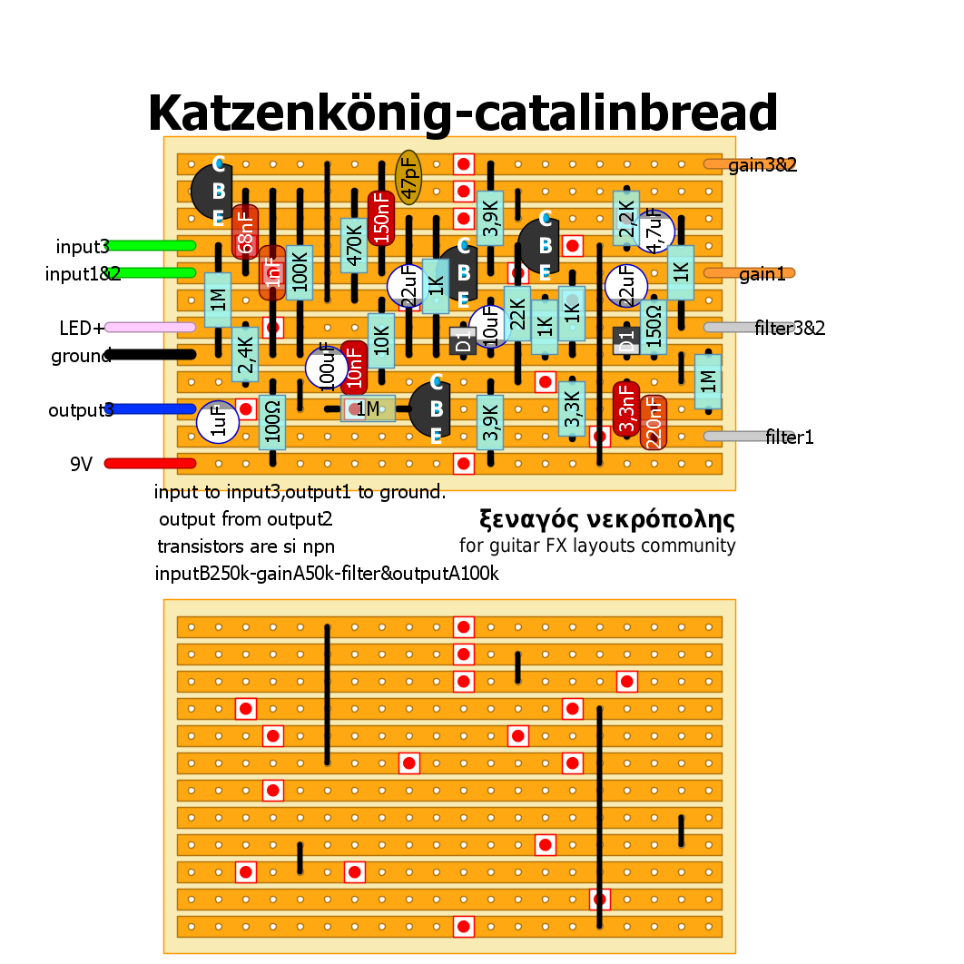
Sorry guys...as it seems , i've got free time, and huge love for this hobby...
updated with the correct 100k as Frank said. thanks mate! 
|
|
Very cool (again!) Savvas. Thanks!
 It would be worth socketing the transistors AND diodes on this. I have lots of parts that could be used and sound good - should be fun. |
|
Administrator
|
In reply to this post by ξεναγος νεκροπολης
Nice job matey

|
|
This post was updated on .
In reply to this post by Frank_NH
Heck yeah! This one if going on a PCB this weekend!!
Whoot! Update: Imported into Eagle, layout created and submitted for fab! Now the wait 
Yeah, 220, 221. Whatever it takes.
|
|
OK - I built this tonight using Savvas' vero layout. Two things....
(1) R2 should be 100K and not 1K (the resistor next to the 1 nF cap) on the vero. (2) I tried different transistors and they didn't want to bias. I tried dropping R9 from 22K to around 2K, and that helped but the sound was still gated. My audio probe indicates that the first stage (Q1) (after correcting the problem with R2) is fine, but that the tone bender stage (Q2, Q3) is not. I've looked at silicon tonebender circuits and it's not clear what the arrangement should be. It seems that R10 (which is 3.9K) is usually << 1K (e.g. 330 or 470 ohms), so I may experiment with that. If someone gets this to works like the video let me know. It's always possible I have a bug in my build... 
|
|
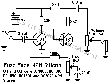
Here is the NPN fuzz face:
 Note the 330 ohm resistor versus the 3.9K in the Katzenkonig. I'm going to try adjusting this resistor to see if I can achieve about 4.5V at the collector of Q3 in the Katzenkonig (my measurements of the current circuit showed much lower voltages, hence the misbiased sound). I'll check everything first so I'm sure there are no other problems with the layout. |
|
The skreddy lunar module is similar, in that it is a silicon mk II sort of fuzz with a rat filter. The Q3 bias is a 2k7 from +9v to the output cap (3k9 here) and a 10k from output cap to Q3 collector (2k2 here).
|
|
Thanks nocentelli. I am using BC108C transistors, similar to the lunar module. What I'll try is to change R10 to ~470 ohms and then see how close I am to getting 4.5V on the collector of Q3. Otherwise, I may just mod this to the lunar module resistor values. Or just build the lunar module!
 Yeah, the Katzenkonig pretty close to the Skreddy lunar module - oh well, nothing is new under the sun as they say... |
|
Tried BC549c, then 2N2222, BC108, BC109c, all gave almost exactly 3.2v on the Q3 collector. None seemed gated, although it was noisy with the input and fuzz pot up (on the breadboard, through headphones). A 10k pot or trimmer across the 2k2 allowed me to dial in anything from 3.4v up to over 5 volts, and it changes the sound a bit, maybe slightly firmer as the voltage goes up to 4.5, nothing spectacular, but it wasn't gatey down at 3.2v.
|
|
This post was updated on .
Curious - have you considered 2N3904 and/or 2N5088?
Some scems I have seen for the TB MK II show the 3904 and a 5088 for Q3 since I do believe the PDF states a modded TB MK II THEN, using a 2N5458 (output stage of the Proco Rat) for Q4 Of course, this is how I'm doing my PCB at least. Ref: http://www.diystompboxes.com/smfforum/index.php?topic=81110.0
Yeah, 220, 221. Whatever it takes.
|
|
OK. I figured out the problem.
Oh Savvas!?  The 3.9K resistor connected to the 2.2k resistor and 4.7 uF cap? It should be connected with 9V and not ground (grrr...). I fixed my build by unhooking the ground end of the 3.9K resistor and running a wire to an empty hole on the 9V rail. Works fine now!  The vero layout should be revised to correct this problem (though it may take some rearranging of several components to get the connection to the 9V rail). Now, it is a bit noisy, and I decided that it was better just running a the input to a single resistor (e.g. 220K) rather than using the input pot. That reduced the noise a little. Proper shielding will take care of more. Also, you can up the power cap to 100 uF or more with a 100 ohm input resistor. I used 3mm red LEDs for my clippers, and they light up nice and bright! Less clipping of the signal than 1N914s. I also found that increasing the Gain pot from 50K to 250K gives you a low gain setting that's in the overdrive/distortion area. Very nice, actually. I would also experiment with reducing the 1K emitter resistor for Q3 if you want the sound less fuzzy. And perhaps also removing the 10 uF capacitor on Q2. Anyways, have fun with this one! |
Re: Catalinbread Katzenkonig
|
thanks for verification Frank !!!
 as i can see now, i've uploaded this one too soon. i had to go to work and i said "it's a small one...how can i screw this up?" well i did.. 2 mistakes in a small layout.... now all fixed, i've added the 100r from supplie and changed that 47uf to 100uf. i'll leave the old layout on. BUT this is the corrected one if anyone wants to build this! verified 
|
|
I'd love to build this one but I have a little bit of a parts dilemma. I am short one 22uf cap. I have plenty of 47uf. Would it be better to replace one of the 22uf with a 47uf or put two 47uf in parallel? I've never had to put electrolytics in parallel before so just to confirm what I read, the positives are both connected together and the negatives are together, right?
|
Re: Catalinbread Katzenkonig
|
hi squirrels.
it's not in parallel. you want them in series. it's not like with resistors. check this out http://www.electronics-tutorials.ws/capacitor/cap_6.html http://farside.ph.utexas.edu/teaching/302l/lectures/node46.html |
|
In reply to this post by squirrels
Yes Savvas is right.
Connect two 10uF together in parallel (The same way round - i.e. both negative stripes on the same side), and you get 20uF, which will be near enough. OR: Connect two 47uF caps together in series(one after the other, + leg of first one soldered to - leg of the other) to get 23.5uF which again is near enough. Practically though, it's usually much easier to fit them in parallel. soldering them in series gets messy, and invites short circuits with other components. |
|
Thanks guys. I should have a few 10uf as well. There should be enough room for two in series if I replace the one coming from the emitter of the transistor on the top left corner if I don't have any 10s. If I'm up to it I'll build it tonight with the updated layout when I get home from work. The only NPNs I have in multiples of four I have right now are 2N4401, 2N5089 and MPSA18. I'm trying to use up some of my parts before I order anything else but luckily for me there is a great electronics shop nearby if I need anything in a pinch but they're a little on the expensive side. I'll let everyone know how they sound. Thanks again.
|
|
I have everything all wired up except for the input. Judging by the schematic its input to input 3 and input 3 to the board, right?
|
|
I have it wired like I mentioned in the above post. Seems like it would be right considering the input 3 connection on the board is just for the pull down resistor. I'm getting nothing except for the LED turning on. Gonna sleep on it I guess.
|
Re: Catalinbread Katzenkonig
|
hi mate.
you're right. i've forgot to write this on the notes as well as the output1 to ground, and output from output2. also i see at the top right, there is a 2,2k that is under 4,7uF cap that looks like 22k. you might want to take a look at this too. i'll fix all of these. other than that the layout is as per schematic. good luck Savvas |
«
Return to Booster, OD, Fuzz, Distortion
|
1 view|%1 views
| Free forum by Nabble | Edit this page |

