Cave dweller II dub edition
|
This post was updated on .
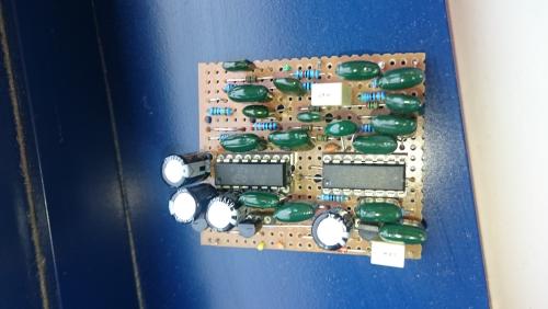
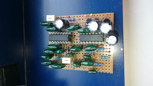
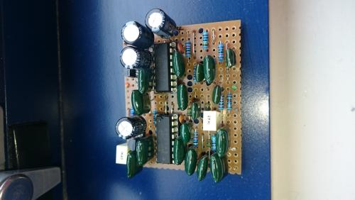
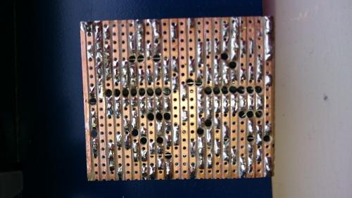
Hi all Finished this over the weekend http://tagboardeffects.blogspot.co.uk/2014/04/madbean-cave-dweller-ii-dub-edition.html and although it kinda works it seems to get stuck in a feedback loop which builds to white noise which makes it unusable. I measured the voltages as follows: Pt2399 1 4.90 16 2.45 2 2.44 15 2.45 3 0 14 2.45 4 0 13 2.45 5 3.06 12 2.45 6 2.43 11 2.45 7 3.9~ (Variable) 10 2.45 8 3.9~ (Variable) 9 2.45 The voltage at pin 7 and 8 changes with the pot position (sorry cant be more specific than that) Just about the same voltages on both chips. Voltage regulator : I 8.22 G 0 O 4.89 Q1 E 0.24 O 0 C 2.42 Q2 E 0.24 O 0 C 2.43 I've checked the layout a bunch of times and I'm pretty sure that the components are in the right places.     Thanks in advance |
|
Your PT2399 voltages look ok, and you're getting repeats, so the PT2399's are working. I can't find a schematic for this circuit (the link in the version 1 layout page is dead), but the symptoms you're describing are mentioned in the dub edition layout page:
"Additionally, the dark repeats have been limited to non-oscillating by using a larger value for R12 . If you do implement the Mix mod, you can lower the value of this resistor from 750k to a value between 470k and 560k to re-introduce oscillation. This is not recommended when not using the Mix mod." Without the schematic I can't be definitive, but you should first verify that the 750k resistor is, in fact, 750k. If it is, try increasing it. Maybe temporarily replace it with a 1Meg pot set up as a variable resitor, dial it in to non-oscillation, read the value from the pot with a DMM, and replace with the appropriate resistor. This should probably work, but I make no guarantees without a schematic. |
|
quote author="induction">
Your PT2399 voltages look ok, and you're getting repeats, so the PT2399's are working. I can't find a schematic for this circuit (the link in the version 1 layout page is dead), but the symptoms you're describing are mentioned in the dub edition layout page: "Additionally, the dark repeats have been limited to non-oscillating by using a larger value for R12 . If you do implement the Mix mod, you can lower the value of this resistor from 750k to a value between 470k and 560k to re-introduce oscillation. This is not recommended when not using the Mix mod." Without the schematic I can't be definitive, but you should first verify that the 750k resistor is, in fact, 750k. If it is, try increasing it. Maybe temporarily replace it with a 1Meg pot set up as a variable resitor, dial it in to non-oscillation, read the value from the pot with a DMM, and replace with the appropriate resistor. This should probably work, but I make no guarantees without a schematic. Thanks, I did read that but it might as well have been in Chinese, looking at it I may have put a 150K instead of 750K, I'm pretty sure that I tested everything before mounting but maybe I misread it, I am soo bad with resistor colours.< |
|
In reply to this post by induction
I removed and checked the resistor and it is 750K, i put a 1M pot in and whilst it made some difference there was still a load of feedback once the mix was about a quarter turn and it was worse when the dwell was turn up. i socketed the resistor and went up to 10M, which again made the problem slightly better but even a small amount of dwell seemed to send it into horrible endless feedback. |
|
Sounds like you have a build problem then. I can't diagnose much more without a schematic, so we'll have to see if we can find a build error by comparing against the layout.
|
No worries. I might scrap this one and re-purpose the IC's for something else. perhaps the deep blue or something. I've been over the layout about a dozen times and can't see anything wrong. perhaps there is a duff component??? Although I did check all the resistors, trannies and caps before putting them on |
|
Oscillating repeats in a delay doesn't sound like a bad component, though it's not impossible. It sounds more like a build error somewhere in the feedback loop. Unfortunately, without a schematic I can't say where the feedback loop is in the layout, so I can't recommend where to start looking.
Higher resolution photos would help. The ones you posted are too pixelated for me to do very much with. |
«
Return to Debugging
|
1 view|%1 views
| Free forum by Nabble | Edit this page |

