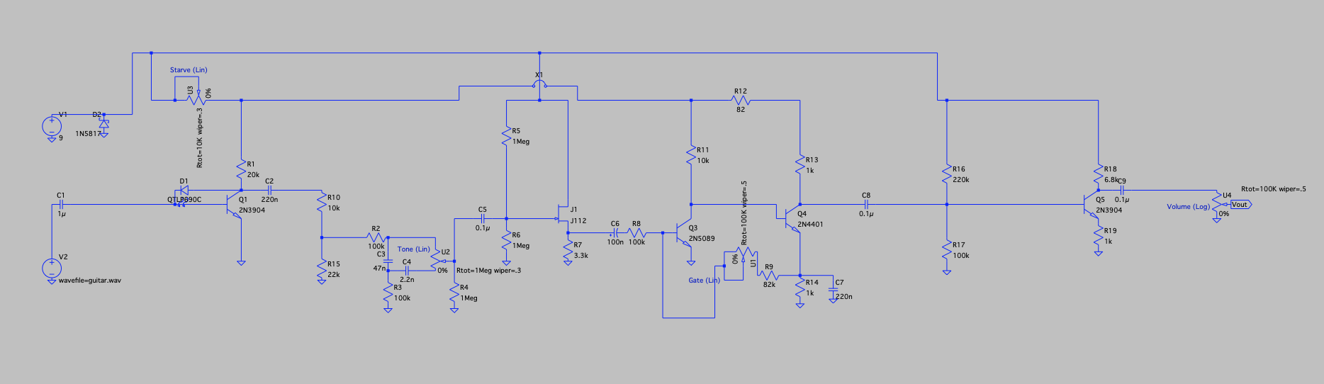
![]() Hi, I have been trying to convert this fuzz pedal schematic into a veroboard layout. Unfortunately, I cannot figure it out for the life of me! Could someone kindly do the veroboard layout for me? Industrialfuzzschematic.png The end result is supposed to emulate the guitar sound used by Nine Inch Nails on Broken. Thank you so much for your help! |
|
If you can wait a while I could to try make this on veroboard.
Can you tell me where this schematic come from?
I build pedals
|
|
Hi,
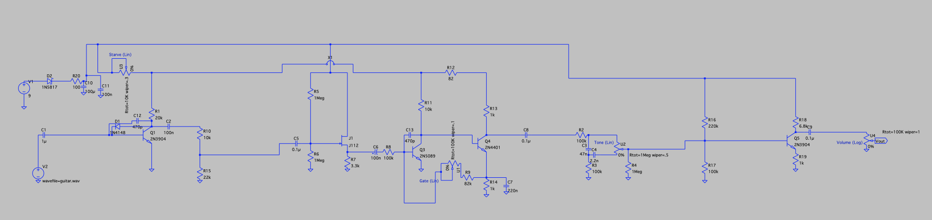
Thank you so much! I put it together. It is a combination of 2 fuzz circuits (a modified Bazz Fuss and a Colorsound one knob fuzz), a JFET buffer, a passive tone control, and a boost. I also added starve and gate controls. I modified the circuits based on research I did so it would sound close to the NIN sound on Broken. |
|
Did you build and test it on a breadboard or something? The tone control behaves a bit weird, and I’m not sure I fully understand how it works.
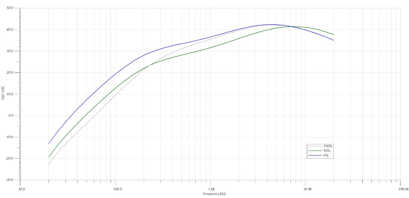
My emulator showed me the response, and it seems to have a slightly weird behavior.
I build pedals
|
|
It worked well for me in LTSpice. What is it doing weirdly for you?
|
|
I'm not sure if the orientation of the Tone pot is correct, but this is what Tina TI show me.
The other pots are at half setting. ![]() In the layout I'd add a 100uF as filter in the power supply section, and maybe the circuit needs an 1M pulldown resistor for the true bypass switching.
I build pedals
|
|
This post was updated on .
Hi,
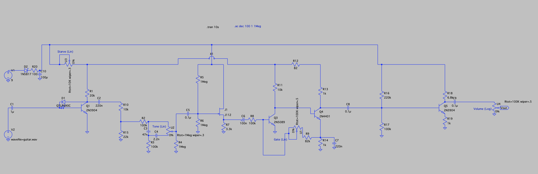
Thank you for guidance. The tone control seems to work better with the 100uf capacitor and a 100ohm resistor in the power supply section as a filter. If you could add that to the vero layout I would really appreciate it. Here is a screenshot of the updated schematic. Thank you again for your help and guidance.
|
|
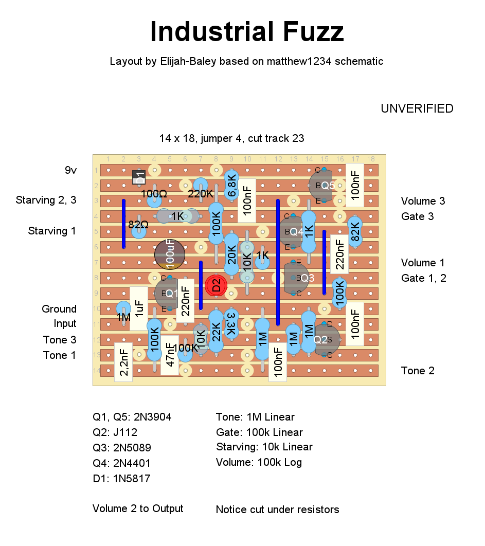
Hi, that's the layout based on your schematic. I just added a 1M pulldown resistor, which is still missing from your schematic.
![]() You can try to build it. I can't see any mistakes, but without actually trying it on a breadboard, I can't really imagine how it will sound. I'm note sure about the orientation of the pots (except the Volume). I notice there's quite a lot of high end, so it might need some filtering. I still have some doubts about the tone control, its action and its position, since it's placed at the beginning of the fuzz section. Usually, it's better to place the tone/EQ section after the gain stages. But... who knows? A gain control is missing as well. I'd probably place it after the first transistor. The 10k + 22k resistors seem to emulate a sort of fixed gain pot. Anyway, that's just my opinion. Let us know if it works well and how it sounds this version!
I build pedals
|
|
Thank you so much for creating the vero layout. I appreciate the time you took to put it together and your guidance. I have learned quite a bit from this.
I will let you know how it works once I build it. |
|
This post was updated on .
Hi,
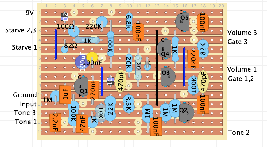
I updated the layout with some filtering capacitors to filter out some of the hiss and radio frequencies. I am attaching the updated Vero board layout and the updated schematic. Could you please look it over to see if it makes sense? Thank you! Vero
![]() Schematic
|
|
I see: you added the 100nF ceramic in parallel with the 100uF in the power section, ok. You replaced the LED with a 1N4148, this gives you less boost and drives the next stage less, but produces more distortion. The 470pF cuts some of the high frequencies, and you also added a 470pF at the 2N5088. You reduced C2 from 220nF to 100nF, which cuts some bass.
At first sight, your modified layout seems fine, except for that 1k resistor, which should be 100k. But in your latest schematic I also noticed that you moved the tone section just before the last stage, which is where the tone circuit is usually placed. I use Tina TI to look at the frequency response, and after moving the tone section I see a lot more signal attenuation and no longer the strong high-frequency peak. This is because the tone control is passive, so it's normal. I just don't know yet if it will sound good or bad. With the tone section in the new position the frequencies look much more balanced now, although the tone control seems to behave a bit strangely to me. At the middle position it looks fairly flat, while at the extremes I get more highs on one side and more highs and lows on the other. Anyway, apart from the schematic, what really matters is how it sounds. Maybe you could try the new layout and socket the two 470pF capacitors you added. If there is too much treble or hiss, you could experiment with increasing one or both of them.
I build pedals
|
|
Hi,
Thank you very much for your analysis of the circuit and reply. Does the veroboard layout still look accurate? I tried to add the changes to it. |
|
Yes, your modified layout looks OK, but I guess you don't need to change my layout so much.
Start from my layout and just add a 470pF capacitor in column 17, between the B and C of Q3, and a 100nF capacitor next to the 100µF, exactly as you drew them in your layout. To add the 470 pF cap between B and C of Q1, just remove the cut next to C, and you'll have enough space to place the cap on the left side. I'd say you can test it like that, if you want, and see how it sounds.
I build pedals
|
| Free forum by Nabble | Edit this page |