Custom Voodoo Labs Pedal Power 2 Plus

classic Classic list List threaded Threaded
19 messages Options
Reply | Threaded
Open this post in threaded view
|

Custom Voodoo Labs Pedal Power 2 Plus

rocket88
Administrator
I came across this on ebay the other day, as I was thinking it might be a good idea to get a brick power supply that has power filtering and what not instead of using my cheap one-spot.

Seeing that they claim its a custom 16 tap power brick, that not only has the normal NPN outputs, but it also has 2 18V ports, and 2 PNP ports, I was thinking maybe someone could recreate something like this on vero. I know a few people have asked about making one, but nothing like this.

Since there are a lot of great PNP pedals having something like this would allow it to be daisy changed, not to mention some pedals that can run on 18V can get the extra power while being daisy chained, Making out lives so much easier and better.

Hope someone on the site has better skill then me and can figure out how to make a layout for this. I can't find any schematic for this anywhere though.
Reply | Threaded
Open this post in threaded view
|

Re: Custom Voodoo Labs Pedal Power 2 Plus

induction
I made something very similar that I use to power all of my pedals. It works very well. I power it with a noisy unregulated wallwart or a laptop supply, and my pedals are dead silent. You can read about it and find the veros here.

It uses a little bit of SMD, but you can easily make the vero one row bigger and use regular through-hole caps instead. You can also customize it to your hearts content (more taps, different regulators, etc.).
Reply | Threaded
Open this post in threaded view
|

Re: Custom Voodoo Labs Pedal Power 2 Plus

rocket88
Administrator
Induction, that's awesome. How easy is it to sub the SMD parts for threw-hole? Also, what about having one of the outputs as -9v for PNP devices?
Reply | Threaded
Open this post in threaded view
|

Re: Custom Voodoo Labs Pedal Power 2 Plus

induction
If you increase each vero strip by one hole, you'll have room to sub through-holes for all of the 100nF SMD's. The SMD resistor can be swapped as-is, but it will stand up.

The link actually shows layouts for two different power supplies. The first one has +9V regulators and a charge pump for +18V. The second one has +9V, +12V, and +18V regulators, and a charge pump for -9V. There's nothing super special about the regulators I chose in each case. You can mix and match regulators as you like, just make sure the adapter you power it has with a couple more volts than your largest regulator. You can use the charge pump for doubling (+18V) or inverting (-9V), just choose the appropriate layout. In either case, the regulator feeding the charge pump should be +9V. The rest of the regulators can be whatever you want.

Don't forget to read the rest of the thread (it's not very long) for some tips about heat sinks, maximum current, etc. Building a power supply like this one (with no direct connection to mains power) isn't any more complicated or dangerous than building a pedal, but there are some things to consider that you don't worry about with pedals.

For instance, the 1N400x diode used for inline polarity protection can only handle 1A max. I know of no pedal that consumes that much current, but depending on what you power with your power brick, you might get close to that. So either run a couple diodes in parallel, or replace them with a jumper like I did. With five 1-amp regulators, you can deliver a lot of current, but your input adapter probably can't source that much current anyway. I included a lot of regulators so I could spread the load around and keep the heat low, but I also heat-sinked each regulator, so they each run a daisy-chain if necessary.
Reply | Threaded
Open this post in threaded view
|

Re: Custom Voodoo Labs Pedal Power 2 Plus

rocket88
Administrator
Cool. Thanks Induction. I read everything and I think I got it, so I made a layout for it. It's the first one I've done, could someone look it over and check to see if I've done it right? I tried to expand it to 6 +9V outputs, 1 +18V output, and 1 -9V output.

Reply | Threaded
Open this post in threaded view
|

Re: Custom Voodoo Labs Pedal Power 2 Plus

induction
You can't get +18V out of a 7818 with only +12V input. You'll need either to power it with +20V, or even better, adapt the charge pump to give you both +18V and -9V.

You can look up the Klon schematic on FSB for help with the latter.

Also, the regulator on the top-right of your layout isn't getting any input voltage.
Reply | Threaded
Open this post in threaded view
|

Re: Custom Voodoo Labs Pedal Power 2 Plus

rocket88
Administrator
Not sure if this is what you were saying I should do, but this looks all sorts of messed up. Would it be easier to just run it at +20V rather than put a charge pump?

Reply | Threaded
Open this post in threaded view
|

Re: Custom Voodoo Labs Pedal Power 2 Plus

rocket88
Administrator
Oh and I tried to make the charge pump from this part of the schematic. I Just really feel like this completely wrong.

Reply | Threaded
Open this post in threaded view
|

Re: Custom Voodoo Labs Pedal Power 2 Plus

rocket88
Administrator
I've been looking at this today, and I hate to admit it, but I cant figure out how to change the 7660s IC to by a charge pump and produce +18V and -9V. I'm just completely stumped how to add it to the layout at the end. Would appreciate it if someone could take some time to do this so the board has 6 +9V outputs, 1 +18V output, and 1 -9V output.

I tried, but I still can't get the hang of creating layouts right. At least I was able to alter the board to have all through-hole components, and partially had it worked out.

I have to take the advice of some people here and try to build a layout from the schematic that has already been done and compare them so I get the hang of what I did right and wrong. I wish I could find a good video on youtube that would help explain how to look at a schematic and determine how to place components, and make cuts.
Reply | Threaded
Open this post in threaded view
|

Re: Custom Voodoo Labs Pedal Power 2 Plus

induction
You're right, your second layout isn't quite right. But don't get too frustrated. You're doing fine. It's a struggle at first, but with practice it gets easy.

Here's a hint. The 
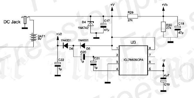
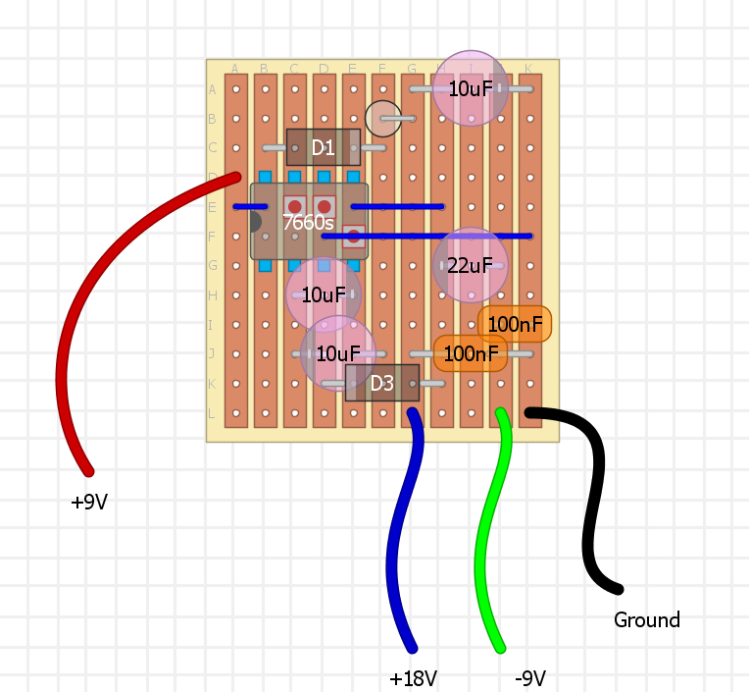
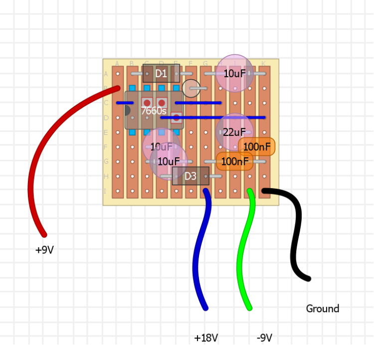
7660s datasheet gives schematics for voltage doubling, voltage inversion and combined voltage doubling and inversion. The doubling schematic has 2 diodes and 2 caps. The inversion schematic just has two caps. Compare the combined schematic to the ones for the individual functions, and you'll find that it's very intuitive: To combine the doubling and inversion on one chip, you just add the inversion components to the doubling schematic or vice-versa.

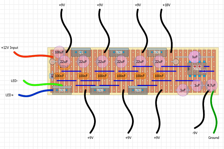
Specifically, take the voltage doubling schematic and add a cap between pin 2 and 4 (datasheet says 10uF, Klon uses 1uF, either should work fine) and a cap between pin 5 and ground (datasheet says 10uF, Klon uses 4u7, take your pick).

Alternately, take the voltage inverting schematic and add the two diodes in series from pin 1 or 8. Put a cap to pin2 at the junction and a cap to ground at the output.

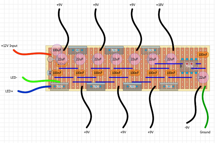
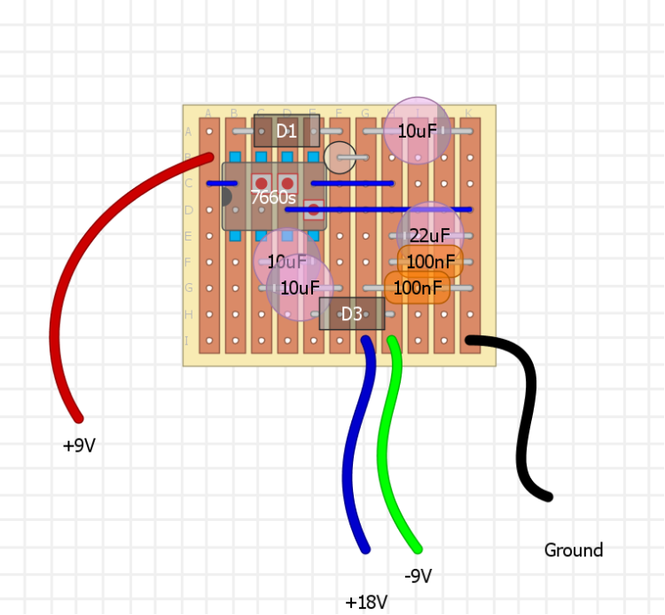
Since it's easier to add two components to a circuit with four than vice-versa, take my layout for the voltage doubler and just add the two caps. Don't forget to remove the ground connection from pin 5.

You've already made the vero one hole taller. Add columns or rows as necessary to fit the extra components. I like to try to keep the vero as small as possible, but it's just a game to me, like a puzzle. Plus, I suck at trying to fit everything in the enclosure, so keeping the vero small makes it easier for me. But the vero doesn't really have to be small as long as you can fit everything in the box without shorting anything. Just use a bigger box if necessary.

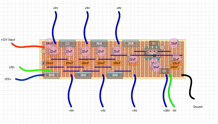
Yes, you can also just use a +20V supply and an +18V regulator. One of my layouts does exactly that. But I prefer to run my 9V pedals off of the other one because the amount of heat generated by the regulator depends on both the amount of current you're using and the amount of voltage you're dropping. There's a formula for this somewhere, but suffice it to say, dropping 11V by feeding 20V to a 9V regulator will produce more heat than just dropping 3V by using a 12V supply. That said, as long as you heat sink the regulators properly, it will probably be fine either way. I just like to stay as far away from failure modes as possible.


Reply | Threaded
Open this post in threaded view
|

Re: Custom Voodoo Labs Pedal Power 2 Plus

rocket88
Administrator
As always, thanks induction. I took a look at the schematics in the datasheet like you suggested, and here's what I came up with for the inverter/doubler vero section. After I was done I compared it to the similar section in your layouts, and added the 100nF caps parallel with the electrolytic caps, but I'm not sure why they are there. Does this look better?


I figure if I got this part right now, and the other half was correct already then I would just have to put the two together. I know the +9V would be connected to the regulator to the left of this section. I would just have to figure out how to cut this part down by 3 rows to make it work.
Reply | Threaded
Open this post in threaded view
|

Re: Custom Voodoo Labs Pedal Power 2 Plus

rocket88
Administrator
Reply | Threaded
Open this post in threaded view
|

Re: Custom Voodoo Labs Pedal Power 2 Plus

induction
You're getting very close. A couple of notes:

1. The +18V part of the circuit looks good.
2. The -9V part is almost ready. Look again at where the -9V output comes from. Also note that the 100nF and the 22uF should be in parallel.
3. I'm not sure what D3 is in your layout. If it is the optional Schottky diode for preventing latch-up (I've never needed it, but it shouldn't hurt anything), then the cathode should go to pin 4 instead of pin 3. You should also note the diode types, for good measure.
4. Don't forget that, like the +9V, ground will also have to be connected to the rest of the circuit. So make sure to leave room for that.

The 100nF in parallel to the electrolytic filter caps are to provide better filtering for high frequencies. In theory, adding caps in parallel just increases the capacitance. But ceramic caps are better than electrolytics at filtering high-frequency noise. Regulator datasheets often just call for the 100nF alone for the output voltage. Putting one of each in parallel should provide better results. Like I said I above, I tend to over-engineer my circuits since I don't have to worry about mass production. I'll just spend an extra $0.007 on an SMD cap, rather than wonder later whether I can reduce the noise and have to open it up and operate on it.
Reply | Threaded
Open this post in threaded view
|

Re: Custom Voodoo Labs Pedal Power 2 Plus

rocket88
Administrator
Cool thanks induction. I put both of those layouts together at like 2am when I couldn't sleep, so no wonder I made silly mistakes like those, cause I swore D3 was connected to pin4 not pin3, and that -9V was on the - side of the electrolytic. Also, I followed the schematic in the datasheet you posted as a link, which is why I included D3, but wasn't sure what kind of diode it should be to be honest. If D3 isn't needed and I were to delete it would I just replace it with a jumper?


Hopefully third time is a charm and then I can try adding this to the whole layout, have it checked, and be good to go.
Reply | Threaded
Open this post in threaded view
|

Re: Custom Voodoo Labs Pedal Power 2 Plus

induction
That looks good to me.

The datasheet identifies D3 as a Schottky, but isn't any more specific than that. You could use any 1N58xx diode. (1N5817 and 1N5818 are easy to find.) If you don't include it, just leave it out. Don't replace it with a jumper.
Reply | Threaded
Open this post in threaded view
|

Re: Custom Voodoo Labs Pedal Power 2 Plus

rocket88
Administrator
This post was updated on .
Cool. Thanks induction. With your help I have now made my first layout successfully. I'll make the complete layout and post it to make sure its all good. That's for all the help. Hopefully I will be able make another one, and with a less help.


Does this look right all together now? *fingers crossed*
Reply | Threaded
Open this post in threaded view
|

Re: Custom Voodoo Labs Pedal Power 2 Plus

rocket88
Administrator
can someone let me know if this layout is correct. If so I will post it on the contributions section.
Reply | Threaded
Open this post in threaded view
|

Re: Custom Voodoo Labs Pedal Power 2 Plus

induction
Hi Rocket. Sorry, I didn't notice you had posted a finished layout.

It looks good to me. Before you post it, I would make sure to label a few things: Q1, R1, and all the diodes should be given values. Two of the diodes have no visible label. I would also make a note of the diode orientation of those two diodes. Put these notes directly on the layout so that after someone downloads it, they don't have to hunt for the information.

Some of it might seem obvious (diode orientation, maybe), but you can trust that it won't be obvious to everyone. Some things, like the current limiting resistor, are fairly arbitrary and can be any number of different values, but if you just pick something safe (like 1k), you will get far fewer emails from people who aren't sure because they aren't quite as experienced as you.

Good work.
Reply | Threaded
Open this post in threaded view
|

Re: Custom Voodoo Labs Pedal Power 2 Plus

rocket88
Administrator
Awesome. I just made those corrections. Thanks induction I couldn't have done it with out you . It's not been added to the contributions.