DBA Reverberation Machine: 6 knobs mod
|
This post was updated on .
I am thinking on building the recently posted Reverberation Machine pedal.
This one comes with 3 knobs: Volume-Blend-Gain. My idea is doing something similar like this Micro Pog mod: 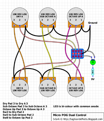 It consists in adding a second set of three pots that would be switched by a stompswitch, so we would have 2 different settings to choose. I have tried to adapt that diagram to the Reverberation Machine, but I am afraid that this is not going to be so straight forward. My main concern is that in the way that I have drawn the diagram, both sets of blend/volume pot lugs that carry the signal that comes from the board, (to be blended or regulated on volume), remain connected all the time, so maybe some signal could be drown to ground by the opposite non selected pot lug which goes to ground, interferring on the pot setting that has been selected. A little hard to explain I guess, but I think the diagram below expresses itself 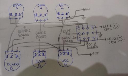 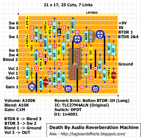 There is a pedal owner at the DBA RM thread, that confirmed that this should be a sick mod for an already sick pedal, so any help would be welcome. Thanks in advance, Gilberto. |
|
Hey.. I had the same idea, to basically have to settings on this pedal that could be toggled between.
Here's a schematic that should work, the schematic drawing makes sense to me, but the vero implementation with respect to the existing vero is bugging me out a little bit. How can I implement these schematic changes to the Tagboard DBA RM verified vero? Here is the original schematic: 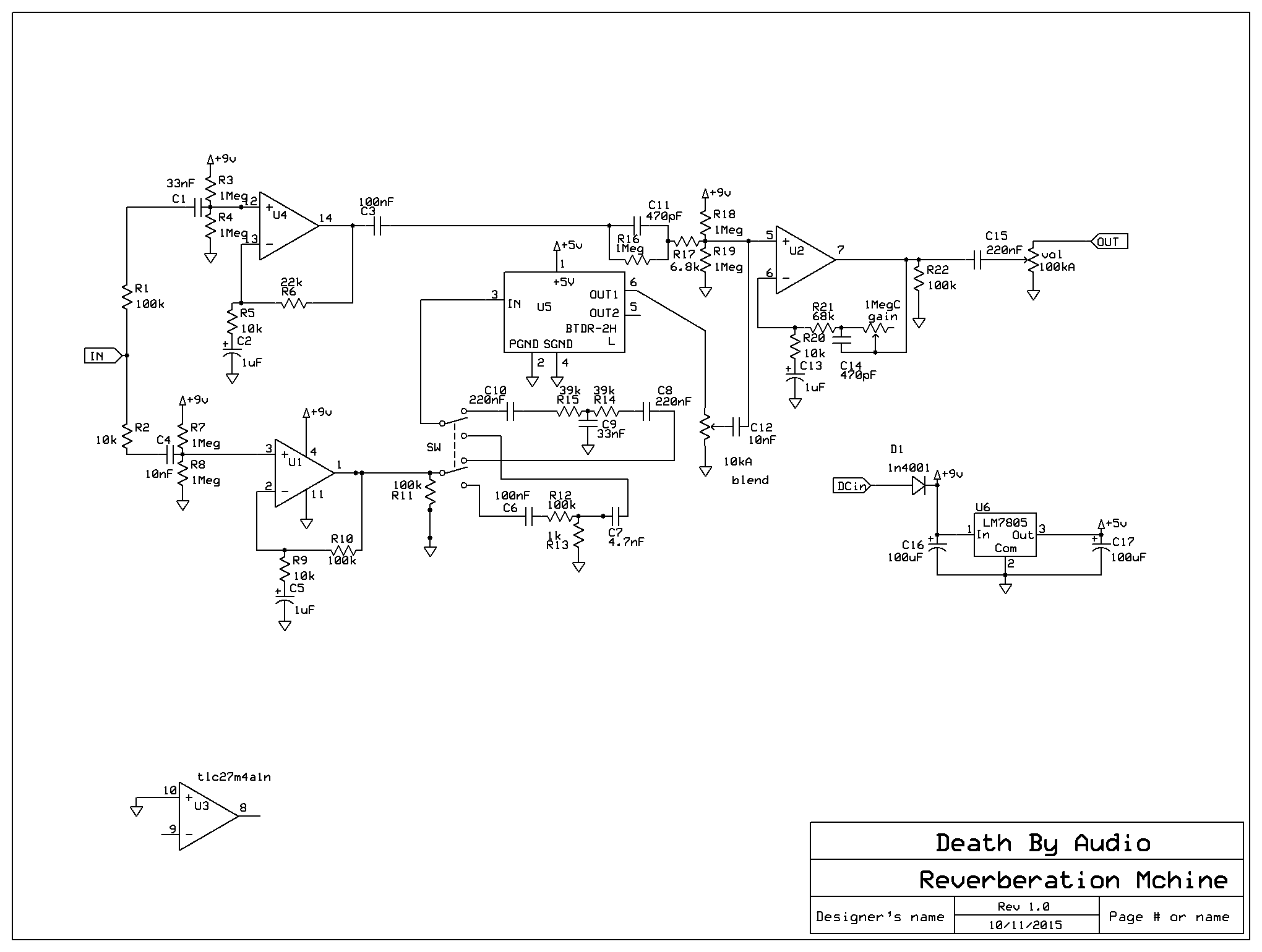 And the modded schematic: 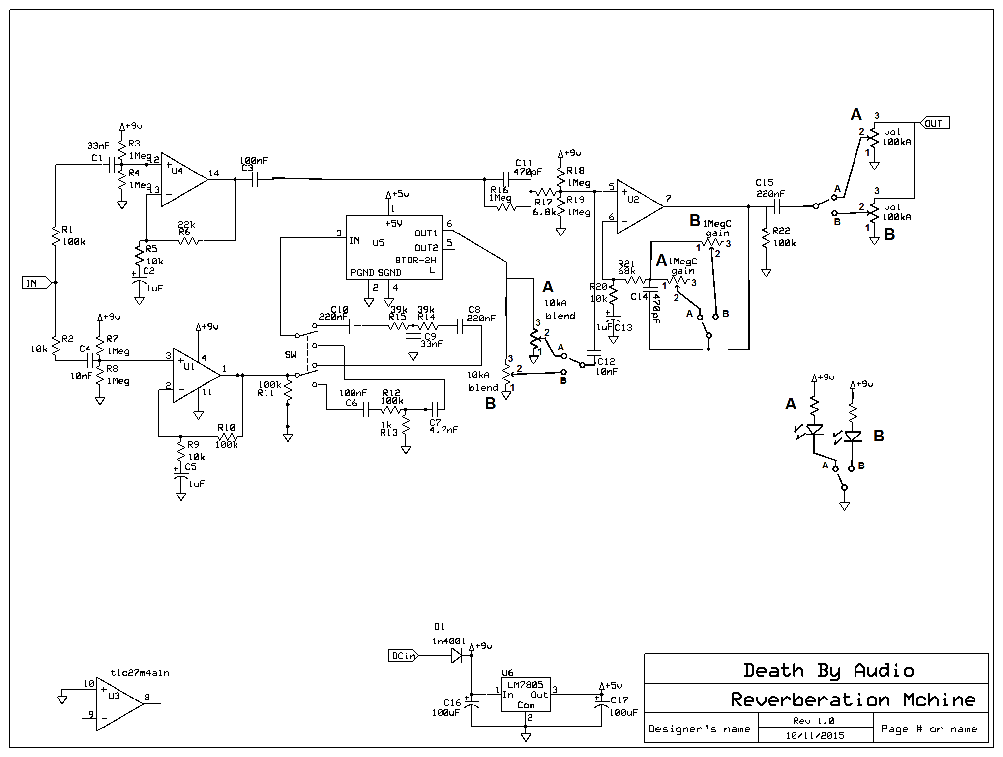 Could someone take the time to edit the existing vero to include these changes? I'm thinking it shouldn't take more than 5 minutes as everything is pretty much off-board. One thought I had is changing the values of the pots to account for total impedance in relevant places in the circuit... halving or doubling where appropriate. What do you guys think? |
|
This post was updated on .
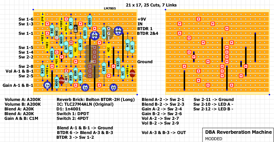
Can't say if it would work or not but here it is:
|
|
Alex, thanks for taking the time! That was fast. You're great.
Is the theory behind the mod sound to you? The mods to the schem look obvious, I'm afraid I missed something obvious. |
Re: DBA Reverberation Machine: 6 knobs mod
|
In reply to this post by traktop
Maybe I'm wrong about this...
But when looking at the Blend pots, and how they are connected in parallel, it seems to me that when having two 10K pots wired like this, it would make the inactive pot behave like a 10K resistor to ground in parallel with the active pot, resulting in a range of 5 to 10K active pot, never reaching 0K resistance. My logic tells me that the switch should be before the pots, in order for it to behave as expected and put out the correct values... |
|
Neil,
you're referring to the Blend pots, right? The others, including the A/B settings stomp, look like they're wired post- switch |
|
In reply to this post by Neil mcNasty
Hi Neil,
I may be confused but if the second pot is like a resistor in parallel it should behave normally, shouldn't it? If you use different values for Vol A & B and Blend A & B in theory it should be ok, right? A 200K pot in parallel with a 200K resistor should give you 100K. A 1M pot in parallel with a 10K resistor should give you more or less 10K. That means Vol A: A200K , Vol B: A200k, Blend A: A10K, Blend B: A1M Gain A & B are ok. What do you think? |
Re: DBA Reverberation Machine: 6 knobs mod
|
This post was updated on .
I'm looking specifically, and only at the Blend pots, and I'm actually completely wrong!
The 10K in Paralell just makes shure that the signal entering the Blend pot in use, allways will have 10K to ground, and that is the same as the used pot at full (maxed/full volume) Lug 2 of the pot in use, still has the ability to connect directly to ground when turned down (shutting the signal off), and will still have a total of 10K resistance to ground when at full, giving the same result as before the modification. One thing though: All pot values should be the same as original, just 2 sets of each of them, connected to the switch. Changing the values will change the behaviour of the curcuit. Meaning that the original values would be the correct values for both the A and B pots. Sorry for confusing the subject! I'm the confused one... |
|
re: the blend pot in the original schematic, at full off the signal goes thru 10K to ground. By adding the second blend pot in parallel with A1 and B1 both to ground wired the way they are in the modded schematic, with either BlendA or BlendB engaged, when the engaged pot is at full off the signal goes through 2x 10k resistors to ground, increasing total resistance at that point in the circuit, right? Even when the engaged pot is at full on, the signal, which would normally not see any resistance when passing thru the blend pot, would also see 10k resistance to ground in parallel... isn't that right?
And since GainA and GainB aren't connected to ground, they're floating, and volumeA and volumeB come after the switch and therefore won't interact with the signal with the other one is engaged, these values would stay stock... Or I could be way off... the way I see it, only the blend pots need to be changed when performing this mod. Hopefully someone can correct me if I'm wrong.. I'm still learning. Thanks guys. |
|
Even more confused now! :)
Blends and Vols lugs 1 & lugs 3 are always conected (1 with 1, 3 with 3). For example, if you switch to Blend B, Blend A would work like a 10K resistor between Lugs 1 & 3 of Blend 2. Same thing for the Volumes. If you use A10K & A1M for Blends you will always get almost 10K, whichever pot you use. If you use A200K for Vol 1 and Vol 2 you will always have 100K. Isn't it correct? |
|
Oh okay.... the way I read the modded schematic was that both blend lug3s are connected, but blendAlug1 and blendBlug1 are connected to ground, not directly to each other, and I would read it as when blendA is engaged, the signal goes through blendA and also a 10K resistor to ground, in parallel. In that case, you'd have to alter the pots to maintain signal impedance after the switch...
You don't read it that way though, right? You have more experience that I do re: this, I am totally comfortable taking your word for it. I'm still waiting for my TLC chip to come in the mail. |
|
Pins 3 are connected.
Pins 1 go to ground, which means they are connected too. The way I see it, the pot not used is like a resistor between lugs 1 & 3 of the used one. But I'm really confused now. Better wait for someone else opinion 
|
Re: DBA Reverberation Machine: 6 knobs mod
|
This post was updated on .
STOP!
Erase everything mentioned above and eliminate all theory. Then start over again from scratch! Right now there are so many wrong things said about this, that it is impossible to wrap your head around it. Do not try to understand the posts above, or you'll go mental... Forget everything dealing with parallel resistance for now. We'll deal with that later (if any such issues pops up as we go forward) in a very simple manner. What to do: Do not change any of the original pot values! Keep them at their original values! There is no logic that says that we need to change those! Just make two set, that are connected via the switch according to the modified schematic above and see what happens. If it works... Great! Mission Acomplished! If it does not work... Just remove the switch and wire it back to normal. Here's what we know: The Gain switching is guarranteed to work, so we can totally eliminate it from our thoughts and move on... We only have to look at the Blend and the Volume pots! This is what we want to know: Can we get away with running just one wire via the switch, or do we need two? All pot lugs going to ground can be ignored when thinking about this, and they do not need to go via the switch. That leaves us a total of 4 wires that needs to be dealt with. 2 for the Blend, and 2 for Volume. Since lug-2 of a pot sets the value of the given pot, it is logical to conclude that this wire (lug-2) allways has to go via the switch for it to work. Fine! We now have only 2 wires left to deal with, and they are the wires going to lug-3 of the Blend and Volume pots. It is now much easier to wrap our heads around this... The question then becomes: can these be run directly to the board, or will they also need to be run via the switch. How do we find out? We try to wire them directly to the board and see if they behave as expected! In the case of it not working: Reduce the ammount of pots connected to the switch (and the led indicator if needed) and select 2 pots to go via the switch instead. Then wire it up again, and you will have acompished your mission. THE END! |
|
This post was updated on .
Have you looked at this?
All the original 3 pots in the Micro POG Dual Control were 5K Lin. They needed to be swapped with 10K Rev Logs to make it work properly. Can read Mark's description: http://tagboardeffects.blogspot.co.uk/2014/05/micro-pog-dual-control-modification.html You need to change the value of the pots. 20K for Blends. 200K for Volumes. |
Re: DBA Reverberation Machine: 6 knobs mod
|
Good point!
Had'nt seen that... Looks like you are on the spot! |
«
Return to Open Chat
|
1 view|%1 views
| Free forum by Nabble | Edit this page |

