DOD FX22

classic Classic list List threaded Threaded
8 messages Options
Reply | Threaded
Open this post in threaded view
|

DOD FX22

Alex
Drawing a layout for this pedal.
I've removed the switching system.
Any possible comment or correction on this schematic would be appreciated
Reply | Threaded
Open this post in threaded view
|

Re: DOD FX22

Ciaran Haslett
That's what I was thinking aye.

I don't think R3 is necessary though.  R41 has no value?  And what is the values of C13 and C11?  I'll start breadboarding tonight and let you know what I find.

Cheers lad
Reply | Threaded
Open this post in threaded view
|

Re: DOD FX22

Alex
Thanks Ciaran.
The layout is finished but I'm waiting to be sure.
R41 looks like a jumper.
C11 and C13 I think they are 220nF caps.
Reply | Threaded
Open this post in threaded view
|

Re: DOD FX22

mirosol
Administrator
Yup. The R3 needs to go. If it stays, there will be vref at the JFET source and that'll kill the signal by completely misbiasing the FET. Also, C13 is best to have nonpolar film cap in there. Same goes for C32. Those caps are 220n and there's been a switch FET between two of those in the original switching, so 220n is the value i'd use for it.

And yes, R41 is a jumper (0R resistor).

Once this is laid out, i'll build one for sure. Love my original but since it's rather expensive and rare, i don't want to use it much... :)
+m
fyaelectronics.com
Reply | Threaded
Open this post in threaded view
|

Re: DOD FX22

Ciaran Haslett
In reply to this post by Alex
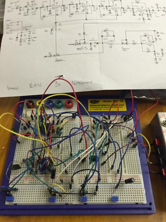
Right lads.  Rats nest done!

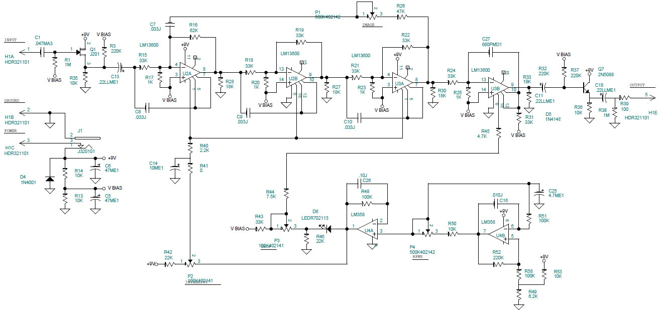
R3 actually didn't make a difference as far as I could hear so probably best to remove it.  All the controls act as they should.  The wains are in bed so I had my test amp pretty low in volume but they all seemed to do what they're labelled as...although I couldn't really hear the "Doppler" effect much.

R41 was happy to remain a link and the caps at 220n seemed fine.

There was a noticeable drop in volume compared to bypass but I was using a BC337 (left most of my components at work and it's all I had on hand)

So I reckon...remove R3 and it's good to go.  

And as a special request...can you draw up a 1590B friendly layout?  Standing resistors, components sharing holes, links on front/back of the board...however ugly it is (not for the main site obviously)...I'll happily build it.

Anyway...glad I could help in any way and looking forward to your layout for the main page. (

Reply | Threaded
Open this post in threaded view
|

Re: DOD FX22

Ciaran Haslett
In reply to this post by mirosol
I should also mention....i used non polar 220n caps as Miro said.

Shockingly embarrassing breadboard pic.....
Reply | Threaded
Open this post in threaded view
|

Re: DOD FX22

nocentelli
In reply to this post by Ciaran Haslett
Ciaran Haslett wrote
All the controls act as they should.  The wains are in bed so I had my test amp pretty low in volume but they all seemed to do what they're labelled as...although I couldn't really hear the "Doppler" effect much.
Intensity controls the depth of a filter-y modulation, drop controls a straight amplitute-modulating trem at the same speed, I found the filtered sound was more noticeable at higher speeds.

Reply | Threaded
Open this post in threaded view
|

Re: DOD FX22

Alex
This post was updated on .
Thanks guys!
I've finished the layout yesterday and thankfully it already had the right components (moving things around would have been a nightmare!).
It's quite big: 30 x 22.
I'm not sure if it would be possible to draw a layout that would fit in a 1590B box.
I'll give it a try as soon as I can.
Thanks again for the help!