DeProfundis Daughterboard

classic Classic list List threaded Threaded
6 messages Options
Reply | Threaded
Open this post in threaded view
|

DeProfundis Daughterboard

jghfslk
Hello Everyone

I am trying to add the modulation daughterboard to my DeProfundis but think I am experiencing some issues others have had.  
The delay has been working just fine.  I seem to be only get two settings instead of three with the modulation.  In the middle setting of the SPDT switch I have my normal delay sound.  In one setting of the SPDT I have the funky mode with all the crazy sounds.  In the other setting I am getting delay only instead of the delay with modulation.  If I am recalling correctly, it is the setting where Sw2 is connected to the ground side of the SPDT.  Can anyone think of a common issue that people could be having?

I appreciate any kind of assistance!

Layout:  http://tagboardeffects.blogspot.com/2014/04/grind-customs-fx-deprofundis-delay.html

Schematic and build document:  https://dl.dropboxusercontent.com/u/28586266/GCFX%20Build%20Docs/PLFOBuildDoc.pdf
Reply | Threaded
Open this post in threaded view
|

Re: DeProfundis Daughterboard

Sensei Tim
necro bump.

I'm having the same issues with this daughterboard.  
Reply | Threaded
Open this post in threaded view
|

Re: DeProfundis Daughterboard

traktop
Having exactly the same problem with my Deep Blue Delay daughterboard.
I´ve been carefully reading the whole deprofundis delay thread where some people had same issue, and some diystompomboxes threads as well, but I get stuck at the same point again and again...(center delay only-one side modulation only-other side delay only)

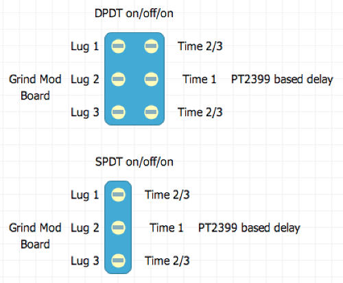
I even drew like 5 or 6 schematics down to paper and I just don´t get it. The thing is that I found out like 3 or 4 ways of doing "delay only"/"delay with modulation" with a spdt on-on switch or maybe a switch for turning on/off modulation with another one to choose between modulation only/delay with modulation but only with a spdt on-off-on is beyond me right know...
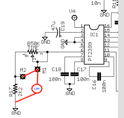
I think we must be failing understanding correctly time 2&3/ time 1 wiring, since is not so clear what goes where and "from where" when we add the daughterboard.

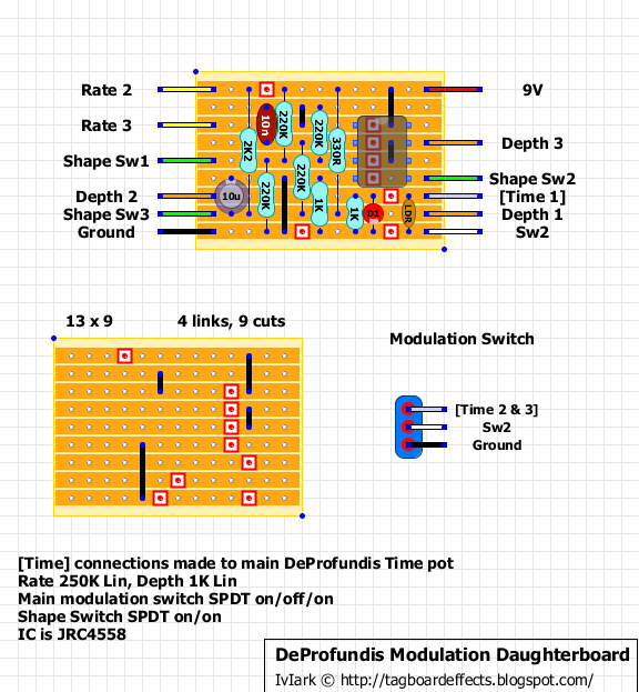
What I seemed to understand is that once we got the motherboard working correctly with all the pots connected and stuff, we just have to connect 1 cable from time 1 and from time 2&3 pots, (or from mother board proper connection points), and connect them to daughterboard time 1 and time 2&3 switch respectively, right? Well, this is obviously wrong, because we have some redundant connections here, like time 1 pot being always connected to ground, (to time1 motherboard), so the ldr do nothing here.

If we connect motherboard time 1 straight to daughterboard time 1, (and nothing to time 1 pot), we get delay with modulation on one side, nothing at center possition, and nothing at the other side as well, (cause delay 1 isn´t connected to anything), etc...etc...


What we need is a "step by step" daughterboard wiring guide for crying supernumbs like us...


Reply | Threaded
Open this post in threaded view
|

Re: DeProfundis Daughterboard

Ciaran Haslett
Did a quick and dirty sim on this LFO.  Based on the switch lugs as per the modulation schematic....

Lug 2 to Lug 1


Lug 2 OFF


Lug 2 to Lug 3


The LFO works fine.

The Time pot on all PT2399 delays is just a variable resistor from pin 6 to ground (with a minimum resistor to stop it locking up).  So all you need to do is bypass the pot (jumper lug 1 to lug 3) and install the mod board as described.  The LDR becomes the "new resistance to ground" and is wiggled by the LED.

Here's a snippet from the deProfundis sheme that makes it more obvious.  Jumper M1 and M2 (bypass the time pot)


So what you need to do to add this mod board AND keep the time pot is....(use either a DPDT or a SPDT on/off/on)


....so the time pot on the delay board is STILL connected as shown on the layout (but additional connections must be made on the switch)

Hope this makes sense.
Reply | Threaded
Open this post in threaded view
|

Re: DeProfundis Daughterboard

Sensei Tim
Ciaran Haslett wrote
great post, Ciaran!

So just to confirm:  


in your switch layout,  Lugs 1, 2, and 3 correspond to Modulation Switch 1, 2, and 3 in the layout?

I don't think anyone had problems getting the square or triangle waveforms - it was with getting modulated delay/dry delay/modulation only.

Reply | Threaded
Open this post in threaded view
|

Re: DeProfundis Daughterboard

BetterOffShred
So I was playing this the other day and it bothered me that It only had 2 delay modes instead of the 3 as advertised so I started doing some searches and came across this...      I know this is some Grave-digger Necro-bump thread status, but hey who cares!? ;)

SO a couple observations...

1.) the way the switch is wired and the LDR... when the switch connects SW2 and Time (2/3) - This puts the LDR in parallel with the time pot, which gives the weird bouncy warbly sounds, and lowers the overall delay time..  

2.) when the switch connects SW2 and ground (the other position), you're essentially putting the LDR in parallel with the 2.2k resistor to ground.. which of course is inaudible.      

My question is, what is the intended strategy?   I figure Paralleling to the time pot is certainly one, should the other position remove the time pot all together?  so you would be connecting the LDR at pin 6 of the 2399, and having it be the only source of resistance to ground?   This would require lifting the ground on the 2.2k

Anyone have experience on this?  The thread kind of died
-Brett