Dimension P Chorus - Parasit - Help needed.
|
Hi All,
I'm trying the Dimension P chorus from Parasit. See: http://parasitstudio.weebly.com/uploads/2/4/4/9/2449159/dimension_p_chorus.png I'm getting a high pitch tone only when engaged. No guitar/chorus sound. I've checked the cuts, bridges and components. Cap polarity etc. All seem ok. I've cut all the suspect tracks for bridges and swapped out the IC's and trannies to check those. It's still the same. I have some [I think] incorrect readings on the IC voltages which may point at what's wrong or at east where the issue might be, but I don't know enough about what the various bits do to know what to check or what might cause the anomalies (other than incompetence)! :) Here're the voltages: IC1 (PT2399) 1. 4.97 2. 2.48 3. 0 4. 0.22 5. 2.37 6. 1.41 7. 2.68 8. 2.68 9. 2.48 10. 2.48 11. 2.48 12. 2.48 13. 2.48 14. 2.48 15. 2.48 16. 2.48 IC2 (PT2399) 1. 4.97 2. 2.48 3. 0 4. 0.06 5. 4.96 6. 0.80 7. 0.57 8. 4.55 9. 4.75 10. 2.48 11. 2.48 12. 2.48 13. 2.48 14. 2.48 15. 2.48 16. 2.48 IC3 (TL072) 1. 7.53 2. 4.48 3. 4.97 4. 0 5. 1.48 6. 1.46 7. 1.48 8. 8.15 Q1 (78L05) (This is read from top to bottom as in layout) 1. 8.53 (out) 2. 0 (ground) 3. 4.98 (in) Q2 (2N5058) (This is read from top to bottom as in layout) 1. 0 (emitter) 2. 0.68 (base) 3. 0.17 (collector) From a check of other voltages for the PT2399, pins 6,7 of IC1 and pins 5, 6, 8, 9 of IC2 seem out of whack and IC3 seems totally wrong? Any comment, help suggestions or pointers in a relevant direction would be much appreciated. Thank you for reading :) |
Re: Dimension P Chorus - Parasit - Help needed.
|
hi mate
i also believe that your voltage readings are a bit strange. i've never build this one, but what you get on those ic's are not exactly what i'd expect. here are some things i spoted in ic1, pin6 is a bit low, and it's strange that you get exactly the same too high readings in both pins 7&8,in all pt2399 builds those 2 pins are around 0,xx so that 2,68 seems wrong but i'm not 100% sure cause as i said i've never build this one. in ic 2 now, pin5 and 8 are too high,6 too low,and 9 should also be around 2,48 in ic3 pins5,6,7 should be round to 4,3 and pin1 is a bit high too... as you can see all these, are things you've already spoted too so...i think you should post some pictures of your board to see if a second pair of fresh eyes could catch the mistake! |
|
This post was updated on .
Hi,
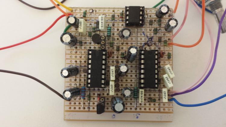
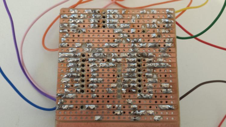
Thanks for taking the time to have a look. This is a bit of a ramble, but I'm trying to add as much info as I can in a bit of a self brainstorm! :) It's one thing reading the voltages and comparing them to spec. It's another finding what's going on without really knowing enough about how electrons are pushed round these things! I'm slowly going through the circuit to try and understand more about which bit is going where [as far as audio and voltage] and in what order, and where it gets split and rejoined (I think that's approximately how it functions?) but it's quite hard for a n00b! I do get continuity and signal at output with the audio probe, but the input is from a tone generator on the PC, so the signal parameters (V, A, W, impedence, frequency etc) are [logically I think they will be anyway] totally different than the guitar signal. (Can anyone suggest the best wave/frequency etc for a tone generator to be close to a guitar output?). The guitar through a guitar amp gives no guitar noise, just the whine. I used log pots, rather than reverse log pots, but I've tried wiring them both ways in case that caused an issue. I don't think it would cause it to just emit a high pitch tone? (which does suggest a short or an incorrect span/bridge?) One other thing that seemed wrong was the orientation of Q1 (78L05) which shows reasonable voltages, but seems to be the wrong way round? I'm pretty sure I've messed this up and counted holes wrong or put the wrong resistor somewhere, but I'm not savvy enough to know what the voltage issues mean? I can't check resistor values with the MM, so I'll have to go from bands,  Here's a front pic.  And a back pic. 
|
Re: Dimension P Chorus - Parasit - Help needed.
|
hi there
from your pics i can see some bad joins man for exsample pin 9 of ic2 which could explain the readings you get. also you have to knife between rows cause i can see some unwanted briges too. just watch carefully and be sure all your joins are strong and correct. |
|
Hi.
Thanks for taking a look. I've run through all the tracks pretty thoroughly, but I'll check them again. I've got a big magnifying lamp thing, but I'm pretty blind so I do still struggle to see if anything is bridged (hence I just blitz them all!). :) I really need to check all the components again, just to make sure they are all correct. This is fun though, isn't it :) |
|
Ok, the good news is, it's all sorted, working and sounds really awesome.
The bad news is, I'm an idiot. I checked all the components three times, cut all the tracks three times and swapped the ICs etc three times. Still nothing. So, I bought a [cheap] USB microscope. Well, I needed an excuse and you can never have enough tools, can you? So I check all the tracks. Nothing shorting. I check a cut and there was the faintest, tiniest, most miniscule strip of copper still connecting. I recut and it works. It sounds really awesome. Did I mention it sounds really awesome? I mean REALLY awesome. It has such a huge range of tone and goes from a really subtle out of phase to a full on organ sound. It's swwweeeettt. Big thanks to parasit studios for putting the layout up. :) If you are in the mood for a nice Chorus pedal (and they [choruses] do seem a bit thin on the ground compared to most other stuff?) I would definitely say this one is worth the effort. Even with all my hassle and chasing shadows, this one has been well worth the effort. So, the positives from this build. I built a fairly complicated [for me] layout I built a really awesome pedal I learned a ton about how these things actually work I found as I learned more about this that I actually know a lot less than I thought I did (From a philosophical perspective, that's good right?) I learned a valuable lesson in humility I learned a valuable lesson in the folly of assumption I learned that, just because you have done something that's really simple 50 times, it doesn't mean you've necessarilly done it properly. Dumbass... And I got my first 'Hey, that sounds cool. Can you build me one?' request for a Love Pedal yesterday. Anyway, It's a bit too late to be drilling now, so boxing up will have to wait until tomorrow now... Jeez, I'm buzzing :D |
|
Ops, just noticed this thread. I guess I need to check the forum more often. :)
Glad you got it sorted! Those microscopic bridges are the worst. / Fredrik (parasit studio)
check out my building blog at www.parasitstudio.se
|
|
Hi Fredrik. No worries. :)
After I boxed it up, it lost all it's chorus sound, so I still have a few things to work out. I unboxed it again, but it's still not back to being a chorus. I'm a beginner at all this, so whilst frustrating, it's all part of the learning process and because it sounded awesome before boxing, I know it's something simple (but annoying :)). I'll get it sorted and post pics/vids... |
|
I know you are dying to read the [idiots] progress, so I won't keep you waiting in suspense any longer.
It's boxed, working and is as awesome as I could imagine it would be. The problem I had after boxing was down to a dry joint in one of the switches. I *think* this caused a reduction in current so although it worked, there wasn't enough ju-ju juice to tickle the two IC's so I got a pretty much un-effected output? |
|
Happy to hear you got it working, all boxed up. :)
That used to happen to me alot.. Boxed up and it would stop working. Sometimes things just short together. Lid off and it works again. :P
check out my building blog at www.parasitstudio.se
|
|
Thanks Freppo. It was my own fault it wasn't working. I guess I got a bit too confident and rushed some mundane stuff.
It's all experience :) |
|
In reply to this post by Freppo
I built this but don't understand how to wire the switches. theres 2 spdt switches but only 4 wires? shouldn't there be 6 wires for 2 spdt switches? im missing something here
|
|
Blimey, this is a blast from the past.
I think the switches are introducing a feedback loops from IC2 into IC1, so they are either open (no signal) or feeding OD-2 back in to the first IC. They are on/on, so it makes sense. No idea why without a bit of reading and thinking, but I think it's fine. I can't find my pedal, so I think I might have lent it to someone or it's in the mess that is my filing system! If I can find it, I'll update. Good luck :) |
Re: Dimension P Chorus - Parasit - Help needed.
|
Just leave lug 3 unconnected. Spdt switches are more common than spst, probably why Freppo used em.
|
«
Return to Open Chat
|
1 view|%1 views
| Free forum by Nabble | Edit this page |

