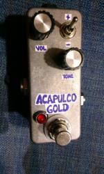
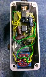
Diode mods for Acapulco gold?
|
I have finished building this circuit and I absolutely love it. Small simple build that sounds amazing. Like I would after building any fuzz/od circuit i socketed the only resistor and tried every different ge led and si diode I had and none of them really seemed to change anything that much. Since my knowledge of diode clipping mods is elementary at best I decided to do some research and I read somewhere changing the diodes after the op amp does not really change the clipping because the circuit uses op amp clipping. Is that true in this particular circuit? and if so what is the diode in the layout for then? just curious because I am a little confused
http://tagboardeffects.blogspot.com/2015/11/earthquaker-devices-acapulco-gold.html#comment-form |
Re: Diode mods for Acapulco gold?
|
Hi man.
There is no diode clipping in this circuit. That diode is solely for polarity protection so that's why you hear no difference. Take a look at a tube screamer schematic. You will see back to back diodes in the feedback loop. They clip any signal above their forward voltage. You see the same thing in a big muff. Then look at the Proco Rat schematic. There's a pair of back to back diodes shunting to ground after the amp. This configuration is known as hard clipping. These two examples are the ones you'll meet most often and are great places to experiment with. Good luck |
|
This post was updated on .
In reply to this post by Fuzzguy801
The reverse power protection diode will have virtually no audible effect on the sound of the pedal; A diode/LED with a larger voltage drop would lower the voltage going to both chips, but you're unlikely to hear any effect from that until it drops below 5v (a starve pot in series with the power suplly might give some nasty gated stuff if you're interested in that). The 386 is an audio amplifier, and this circuit just uses the first 386 run at high gain (which will clip when the stings are hit hard) straight into the second one, which is run at a lower gain but pushed into clipping by the first chip driving the input so hard. There is also a 4n7 cap to ground on the second chip's input to bleed off some treble to keep down the hiss and noise from all that gain. You could play with that value, but it just means more noise and treble, or less noise and woolly. You could add additional clipping by connecting diodes to ground after the output cap (i.e. an antiparallel pair from volume lug three to ground), or modify the amount of amp clipping by adding series resistance between pin 1 and 8 on either or both chips. It's not usually used as an opamp like a TL072 etc, with the gain controlled by feedback from output to inverting input: the gain here is controlled by resistance between pin 1 and 8: Check the datasheet for a proper explanation of how it works, but essentially, leaving the pins open gives you fairly low gain (pretty clean with gentle strumming using low-ish output pick-up), directly connecting pin 1 and 8 (usually with a large electro) gives a ton of extra gain, and a 5k pot allows you to control the amount of gain. Tim Escobedo and others have implemented different gain controls for the 386 as well - look up "circuits snippets" for some very cool simple circuits to play with, including a number using the 386 as an input boost/simple fuzz stage. I tend to find these types of 386 dirt circuits work best at full tilt: The note decay on these 386 chips is something i've never managed to get sounding good, i.e. it's usually a bit gated or has a noticeable "drop down" from distorted to clean when a hard plucked note fades out; They don't really do "subtle shades of overdrive for me (I'm not sure whether you need to try out lots of different ones from various suppliers, or get the power really clean but i've never had the patience to spend a lot of time with them). Having said that, for an easy mod i would try out a 5k or 10k pot connecting pin 1 and 8 of the second 386 chip using lugs 2 and 3 (left and right-hand end of the top row) for an "insane extra gain" level control. You can always turn the guitar down to reduce the amount of filth, this would allow you to turn it up. |
|
In reply to this post by Fuzzguy801
The guys are right, it will have no audible effect on this circuit.
I suggest you build something like the Univox Square Wave Fuzz. It's a simple, great sounding circuit, but more importantly a great test bed for different diodes. It would b a great learning tool for you. If you socket the diodes, you can try all sorts of different silicon and germanium diodes and Schottky diodes and listen to the different sounds they produce. You can also try it just one diode (you will notice a difference between north and south orientation), or with three (two north, one south, or two south one north) for assymetric clipping. This is the circuit I used myself to "learn all about diodes". |
|
In reply to this post by Fuzzguy801
I recently built an "acapulco gold" on a 1590a.
  I replaced the 68k resistor by a 100k pot as a sort of tone knob, (worth doing it). There was a mod suggested on the thread that I made as well. I wired both +iNPUT/-INPUT of the second 386 to a dpdt and made it so when +input is selected the -input goes to ground and viceversa. That way I can use one input or the other, (I don´t find this mod useful at all, since both inputs sound like... the same?¿). I tried a gain 1M pot at the circuit input, but it sounds like poo poo to me... Throwing it into an already cranked amp could be useful since you get more harmonics, (thing which I suggest strongly to make this pedal really sound terrific in general). I always thought on using the gain stage of the second 386 just like the first one; with a 10uf capacitor in series and a pot, but I really ran out of room in there... Post your findings on this one ;) |
«
Return to Open Chat
|
1 view|%1 views
| Free forum by Nabble | Edit this page |

