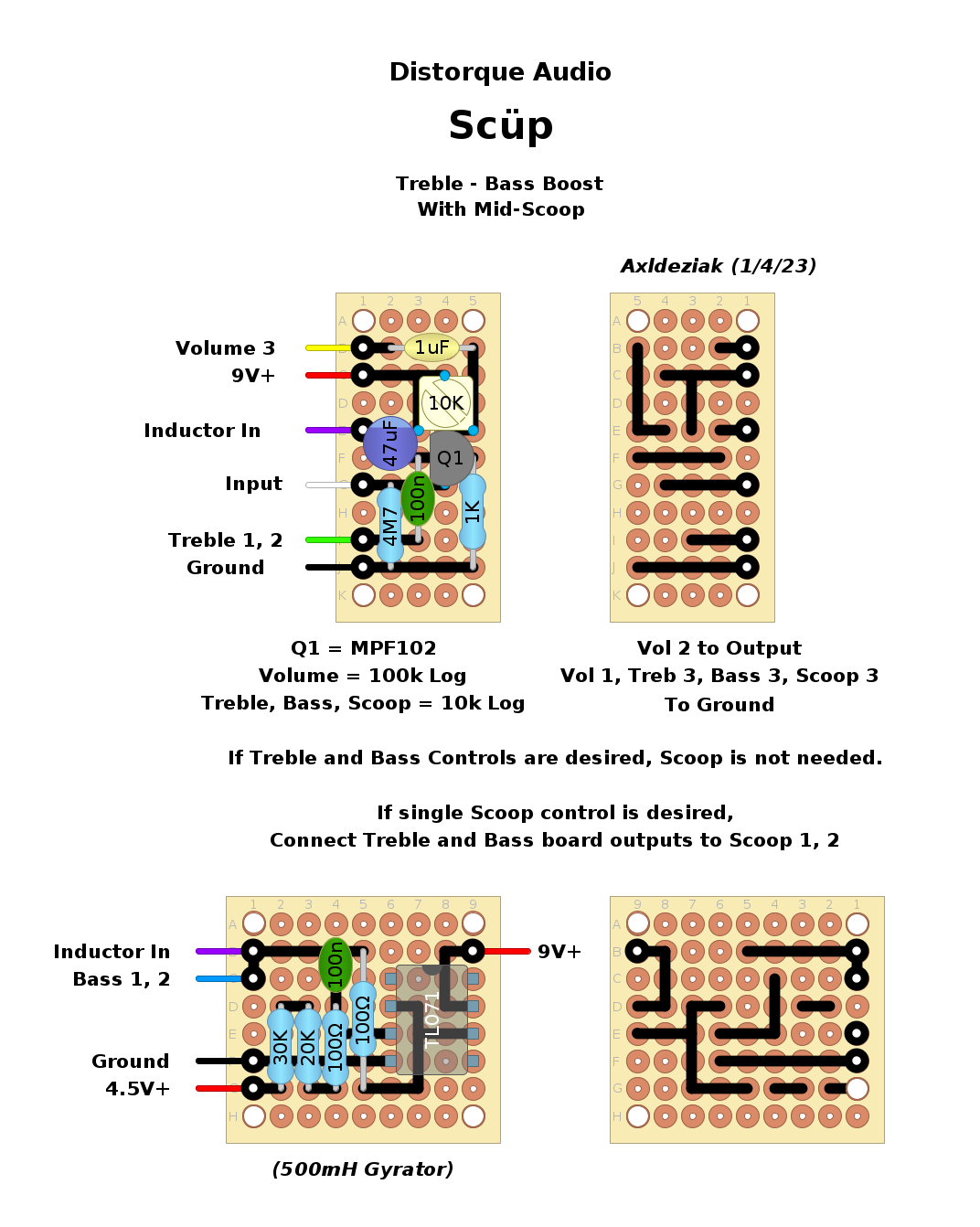
Schematic can be found
here.
The original schematic calls for a 500mh inductor so I have replaced it with a board for a gyrator.
The first layout follows the schematic with a 10k variable resistor to the drain of the Jfet.
Since the exact function of the variable resistor is not given, I took a guess that it was to bias the fet drain at 4.5V.
The second layout forgoes that variable resistor and is drawn up to be connected to a bog standard voltage divider.
