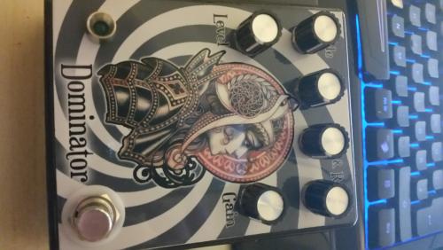
Dominator
|
hi there,
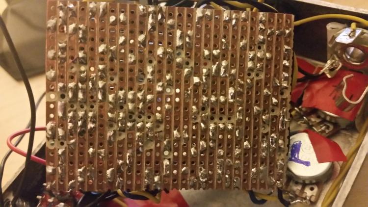
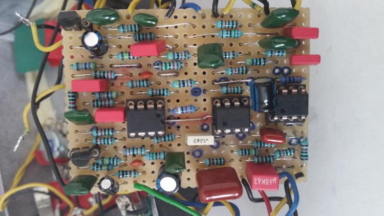
the Dominator is my sixth build and the third made on vero.  layout and offboard wiring from this site. Parts, placement, bridges and cuts are checked. so is the wiring. bypass signal is positive, led is on, but no effect. got bf245a an op2604 and two tl072cp, powerboard has the icl766s ond the 78L15 instead of 1k resistors they gave me 1,2k - should this be the error already? but first of all Grounding question. The site wiring shows me input(jack)/output(jack)/switch to the 9v plug ground. and a seperate 9vground to the board. which one is the best? powerboard ground to board ground to 9v? each board seperately? tried both, well it needs ground of course, but no effect. Im in vacation the next days so i will replay late, also got no tools to measure the IC etc. but i will have after my vacation. so here are pics of the Powerboard and the Board itself. maybe i´ve overseen something.     many Thanks in advance |
|
hi again. i could not wait, so i bought me a multimeter.
and found a bug on the powerboard 9v goes in but 8,8v come out instead of 18v and 15v. so i will investigate on the 7660s chip. i soldered the chip directly to the board, think it wasnt a good idea... to be continued... |
|
Administrator
|
In reply to this post by loder
The way you described the grounding is a little confusing to me. All grounds should be connected to each other, and they don't connect to 9V at any point. They connect to either the black wire of the battery, or the center of a normal boss type power supply (the bigger lug on your switching DC jack)
|
|
Sorry for my bad english.
DC Jack ist the Name of what i call a 9v Plug. With everything grounded the led wasn´t working anymore, but without. Thats why i asked the stupid Question about the best Grounding way. a little more investigation showed me that the ic also gave me 8.8 V to Ground. (bridge Pin3 to Pin8) in fact every pin gave me some output. I "forgott" that the led had its own circuit. So i guess i have an buggy IC. Hope that was it. i will report any progress later on im in vacation the next three weeks. Thanks for your reply |
|
Administrator
|
I don't think you're asking stupid questions
The pinout of an IC is numbered in a "U" shape like this. The dot and/or indentation on the package indicates pin 1. 1 8 2 7 3 6 4 5 So the link on the charge pump actually goes from pin 3 to 5. And you may also notice that pins 1 and 8 are connected to engage the frequency boost on the 7660S so that you don't hear a whine. The 7660S is one of the parts in this circuit that is most susceptible to failure. It would be a good idea to use a socket, though there could be a wiring issue causing your problems rather than a faulty component. The parts of the charge pump circuit where you should test the voltage are the I and O pins of the 78L15. At the I pin you should get approx 18V. At the O pin you should get just about exactly 15V The fact that the LED doesn't work when grounds are connected indicates a wiring problem. Maybe post some pics showing the wiring so we can take a look |
|
thank you very much
yes you are right  i mean the bridge from 3 to 5 of course and both pins gave me ca 8v with 9v input at pin 8 and the row to pin 5 is described to go to the ground (shown in the grafic on this site) which is wired to the dc jack ground. checked if any other dc input is wired to ground. but seems good, chances are high i fried the chip. anyway a socket and new chip :) to be continued... |
|
hi there,
back from my London vacation - and a short update. Fighting the jetlag active - with new parts and a small success soldered a new sockett, placed a new 7660s. - no Change......  Then after half an hour of swearing i saw that on of the diodes was placed wrong (checked that thing about 50 times i think)......  , placed it right and .... tadaaaa we have 14,4v and 16,6 volts and nothing on ground. , placed it right and .... tadaaaa we have 14,4v and 16,6 volts and nothing on ground.
plugged to the "amp" [(i use S-GEAR with an SHO-clone (from here of course) as a preamp into an ESI Julia Card )] First thing : Level and Gain work reverse  second: the tonestack seems to work not at all. This build surely is a Beast. so next to do: check pots :( check wiring (again.........) (sometimes i think this is my first pedal not my sixth - and i´ve successfully finished the tremulus lune before this - worked instant, just swapped the 4885 for eliminating the "pulsating") Well the 14,4 volt seem to be ok, but what about the 16,6 its not even near 18v. after all the distortion lvl is fine i think and not in the fuzz area. From thursday on i am again off for vacation for a week so i will reply late. Thanks in advance for any ideas & help. to be continued.... |
|
checked pots value
rewired everything so the pots won´t work reverse. changed the 1,2k resistors to correct 1k. only gain and lvl are "working" - tone ones seem to do nothing at all gain is grainy. chances are high i got a misplaced part on the board (see diode powerboard) will unwire everything and start checking the board from scratch. |
|
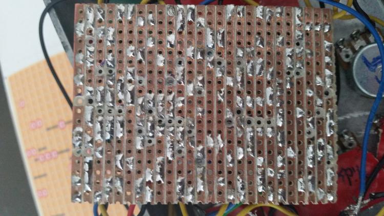
Maybe a silly suggestion, but did you knife in between the rows yet? It's hard to tell, but on some of the cuts it looks like there sometimes is a bit of stray copper sticking out and touching the other row. My eyes could betray me ofcourse.
|
|
Thank you for the tipp. Not a stupid question at all. it is a common error on all vero builds even so wiring with shielded cables and just one fine straw reaches the ground and kills all of the effect section - funny times to find that straw :)
So what ive done untill my last post: Effectboard: Unwired everything, Checked Position and and value of all parts by the colours of the resistors and the stamps on the capacitators (i used some bought of ebay so they could be faulty), cut the rows again and checked with magnifier. Checked all bridges and cuts (as far as i could see them). Rewired everything again into box Status Quo: Level and Gain "work" there is distortion and loudness by the turn of the potis but they need to be pushed a bit before the effect works. this time not grainy. also no Deathmetalbrutalhighgain but pretty highgain. and overall dull and lifeless but i m sure this is due to the not working area --------> EQ section doesnt seem to work at all. in the next post i will have measured the ic´s and the transistors value. to be continued.... |
|
Yes i can see that the OPA is placed upsidedown, but thats only on the picture. for the testing i turned him right.
Just as a reminder, im still a noob and this hobby is a bit more of electric LEGO to me. (ok a little more do i have learned) but still im pretty noob :)    So here are the results: Powerboard: 78L15: I:16,52 G:0 0:15,04 7660s: 1:8,99 / 2:4,24 / 3:0 / 4:0/ 5:0 / 6:4,53/ 7:3,87 /8:8,99 Effectboard: bf245a: Left D:4,90 S:1,61 G:0 Right: D:11,45 S:6,69 G:4,71 IC1 (OPA2604): 1:7,21 / 2:7,23 / 3:6,54 / 4:0 / 5:7,20 / 6:6,22 / 7:7,19 / 8:14,45 ic2 (TL072) : 1:8,30 / 2:8,30 / 3:4,12 / 4:0 / 5:4,05 / 6:8,28 / 7:8,29/ 8: 16,54 ic2 /TL072) : 1:14,89 / 2:14,13 / 3:14,07 / 4:14,69 / 5:14,20 / 6:15,95 / 7:15,94 / 8:16,54 so i can see the three gain stages here on the ic´s i think and the lack of gain resulting to the 16,54 peak instead of 18v? Well after all i´m stucked here. i would be thankful for any help or advice tomorrow i`llbe off for another week so response will be late Thanks in advance |
|
Back again,
this time i will check the components via multimeter, check for anything touching ground, any straw of copper touching anything that it shouldnt. i would be thankful if anyone could tell me if the 16,54 of the voltage doubler is ok or the powerboard still is the weak spot. |
«
Return to Debugging
|
1 view|%1 views
| Free forum by Nabble | Edit this page |

