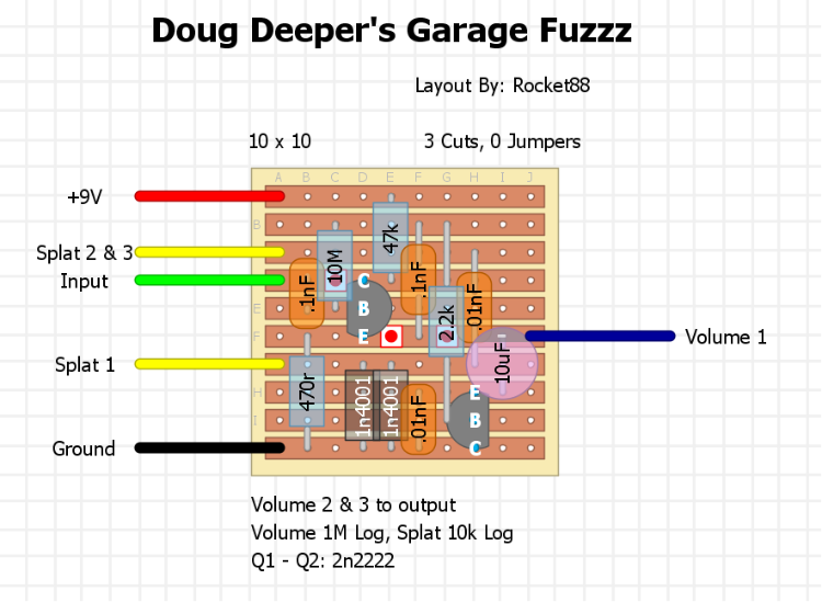
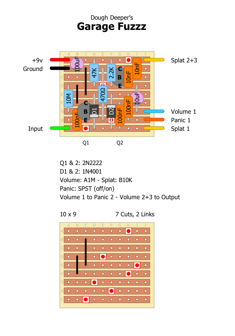
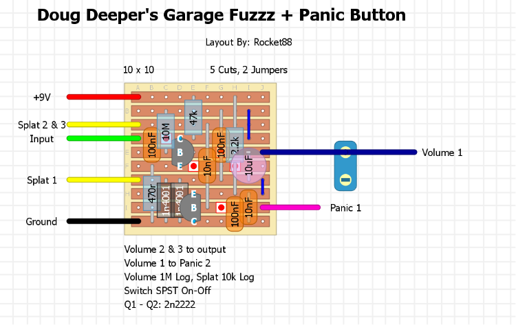
|
Administrator
|
fulfilling a request. this is supposed to be reminiscent of the old school dirty, nasty, sputtery fuzzes of the 60's.
layout according to the posted schematic, but with a splat control to control the amount of fuzz ![]() layout according to the posted schematic, but with a splat control to control the amount of fuzz, and add "panic button" which creates more fuzz and induces feedback
|
|
Nice add, the version with controls and panic button is a must!
|
|
In reply to this post by rocket88
What transistors should be used?
Keith
|
|
2N2222
|
|
Thanks
Keith
|
|
Administrator
|
shit, i didn't realize i forgot to put that on the layout. now its added.
|
|
Is this verified? I tried tonight and can't get it to work. I triple checked my work (with a break in between) and I can't find any fault.
Keith
|
|
Administrator
|
i didn't get a chance to build it, but it should match the schematic exactly. let me take a look at it again and make sure. did you check the layout against the schematic too? which one did you do, the modded or the normal? also, are you getting any sound of of it or nothing at all?
|
|
Administrator
|
here's what i found could be. it's hard to tell on the schematic if the 10M is connected to the 47k to the collector of Q1 or not. also, the 2.2k should go from +9V to E of Q2. here's a correct layout to reflect these changes.
New Corrected Layout: i'm 99% positive this one should work. ![]() New Corrected Layout With Panic Switch: i'm 99% positive this one should work. ![]() here's the schematic so it can be checked too. ![]() the board must have moved while i was moving components and didn't realize. |
|
I wasn't getting any sound out of it. I'll try it with the changes tomorrow. I'd just fall asleep and burn myself if I tried it now. I may be out of 2n2222's so I might try 4401's or 3904's until I can get restocked. Thanks for making the changes
Keith
|
|
Administrator
|
keith i thought you socket your transistors? i always do to make sure i can always take them out even if i need to scavenge to test a new pedal until i can get more. just do me a favor and check that it matches the schematic. after the stupid mistakes that happened on the first one, i checked the new ones 10x, no joke, but it would be good to have another set of eyes give it the once over. i'm still 99% certain it should work now.
|
|
I normally do when I think I might try different transistors. (I always socket IC's) but if the tran choice is pretty solid, I just solder them in. I just don't keep any stock of 2222's because I don't use them often and they are expensive (relative to other trans) On the other hand I have a shit ton of 3904's which I like the sound. I will socket this one becuase it might be fun to try some different stuff. Would an NPN germanium work?
Keith
|
|
I am not shure if you got that layout right.
One error is the 0.1uf at the end... It says in the documentation, that it should be a spst (simple on/off switch) that connects the 0.1uf cap to ground. Meaning: attach one leg of the 0.1uf cap after the 10uf cap and the other leg to a switch that connects to ground. It would be cool to use a momentary stomp (normally off) for this one so that you can kick in oscillation/chaos with the stomp of a foot... Anyway, after looking at the layout, wanting to build it, but not being able to wrap my mind around it... I decided to make a layout myself, in order to familiarize myself with the circuit. I am about to build it now, so it has not been verified yet... I'll be back after building it with a report... Here you go:
|
|
Administrator
|
This post was updated on .
shit, this is what i get for doing it late at night when i can't sleep. i miss read if some how. i made the change on my layout above. now they should be correct. i check and since i'm wide awake, it should be good. lol
|
|
he, he...' sounds like me.
Lately I've been up until 5 in the morning almost every night, not being able to stop tinkering and building. This is highly addictive! Anyway, just discovered a small error in my layout above (2.2. had become 22k), but it's fixed now. So now that we have two layouts, it's going to be interesting to see if we both got them right... :-) I'll be firing up my anytime soon... |
|
Administrator
|
i hear ya, lately i just can't sleep. i think it's the long summer vacation. it's driving me nuts. btw, i caught another error mcnasty, the output cap should be 10uF electrolytic not 100uF.
|
|
In reply to this post by rocket88
I tried the newest layout and still no sound. I don't know enough about it to comment intelligently, but it's probably one nagging little thing. Anyway, keep plugging at it.
Keith
|
|
in the newest mcnasty layout everything is correct except for the 10uf out cap... the negative leg should lead to volume 3, out to volume 2, and volume 1 to ground.
oh, and the panic button mod is all wrong. a 100nf cap should lead from the negative leg of the 10uf cap directly to an spst, and the other spst lug goes to ground. so... move the top lead of the 100nf cap (thats one column to the left of the 10uf) two rows down... so that the 100nf cap spans between the negative leg of 10uf to the "panic 1" wire. |
|
Administrator
|
adapt, it says in the notes of the schematic that a volume control shouldn't be wired the way you normally do, and that it should be wired like a variable resistor instead, because if you do it the traditional way it will just change the frequency of the oscillations, and oscillate when you're not playing, so i don't think that's the problem.
i looked at the wiring of the switch and when i read it, and your explanation i think it should be wired like this.
|
|
My layout did not work.
I am pretty sure i got everything correct according to the schematic, but still... Completely dead! I'm starting to suspect that this schematic might be just based on a theory. It would probably be a good idea to test it on a breadboard and see if the circuit actually works. Anyway... Will keep tinkering with it and see what happens... |
| Free forum by Nabble | Edit this page |
