Dr Boogie build issues


|
Hello all, my request is one for some help with a Dr Boogie pedal I have been building.
Here is the relevant information. 1.What does it do, not do, and sound like? - LED lights up, bypass gives no sound (audio in not working) audio out works (when unit is engaged, and tip is touched, gives tapping noise) also when unit is on, there is audio interference, but only from the board out. The only pot working is the volume which is connected to the mono out jack. 2.Name of the circuit = -Dr Boogie V2 3.Source of the circuit (URL of schematic or project) = http://tagboardeffects.blogspot.ca/ Saturday March 10, 2012 (one needs to go back through the posts to this date to find the layout) 4.Any modifications to the circuit? Y or N -Added a DC jack -installed a stereo (TRS) input jack 5.Any parts substitutions? If yes, list them. -1.8k (instead of 1k) resistor tied to a blue LED. -Shielded audio input, with ground from cable attached to ground on board -Treble pot is a 50K linear (calls for logarithmic) -mid pot is a 2k linear 6.Positive ground to negative ground conversion? Y or N -Not to my knowledge 7.Turn your meter on, set it to the 10V or 20V scale. Remove the battery from the battery clip. Probe the battery terminals with the meter leads before putting it in the clip. What is the out of circuit battery voltage? => -9.44V DC Voltage at the circuit board end of the red battery lead = 9.19V DC Voltage at the circuit board end of the black battery lead = No reading, my black lead coming from the battery snap, is attached to input Ring (TRS) on my stereo input jack. Q1 D- .99V DC S- .28V DC G- .29V DC Q2 D- 1.01V DC S- .30V DC G- .30V DC Q3 D- 1.26V DC S- .55V DC G- .56V DC Q4 D- 7.78V DC S- 6.90V DC G- 6.96V DC Q5 D- 8.58V DC S- 7.78V DC G- 7.77V DC I have gone through all the debugging steps I can find, everything works, except audio in. board is powered, and I made an audio probe, connected to my amp, and poked around. Nothing at all, save for some sound variances (like signal reduction when you touch ground). I have a feeling it may have something to do with th3 way my switch, 9volt clip, and dc jack are wired, in relation to my input and output. The input from the board itself runs to the 3pdt switch, and the output runs from the board to the Volume Pot, second lug. Everything else is wiried as in the image above. Any help is appreciated 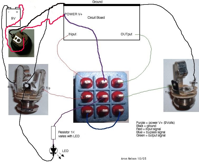
|
|
|
This post should probably be in the "Open Chat" section ("Requests" is for vero layout requests). That's OK we can help here too!
First and foremost, check your bypass. Get some alligator clips and set your DVM for continuity check. In bypass mode, there should be a straight connection from input jack to output jack when both jacks have 1/4" plugs inserted. I think your problem is with the blue wire at the bottom of the switch, maybe a bad solder joint. In any case, use you continuity check to find the break - should be easy. Next, with the effect engaged, use you audio probe to listen to the circuit from the input of the circuit on the vero through to the output. Again, if there is a break you should be able to find it. Cold solder joints can cause problems like this when you don't hear any signal at the output. Your transistor voltages don't look right at all (except Q5, which should be at around 9V since it's a source follower). Your drain voltages for Q1 - Q4 should be about 4.5V - 5V (~half the supply). You will need to adjust the trim pots to achieve this. So set up your DVM to read DC voltage, attach the - probe to ground with an alligator clip and use the + probe to measure the J201 drain voltages while you adjust the trimmers with a screwdriver. Later on you can tweak these a little by ear to get the best sound. If you can't achieve 4.5V or thereabouts, something else is wrong (could be the JFET...). This should keep you busy for an evening. Post a picture of your board if it still doesn't work. Good luck! 
|
|
|
I verified the connection with my DVM between the input and output. I get continuity between the 2 lugs on the switch, and a further check, gave me continuity from the input to the output jack (Input tip to output tip, input tip to output ground, input ring to output tip, input ring to output ground, input sleeve to output tip and sleeve) The only difference with 1/4 inch cables not attached, is that I do not get continuity from input ring, to the output. I used the audio probe to tap into every available spot (a jack from my guitar, to the input, effect engaged, audio probe 1/4 inch end into my amp, probe from the board to amp input) I do get some intermittent noise changes, but nothing I tapped into gave me any guitar or effect tone while strumming. The noise changes are reductions in treble, or volume drops. I biased the JFETS, and have some new readings, though the last pot doesnt seem to impact Q4., I also checked the 100ohm resistor, and am reading 8.17V DC on the input side, and 8.62V DC on the other side (using a boss 9v adaptor) New readings are as follows. Q1 D- 4.75V DC S- 3.96V DC G- 3.96V DC Q2 D- 4.87V DC S- 4.09V DC G- 4.11 V DC Q3 D- 4.56V DC S- 3.80V DC G- 3.81V DC Q4 D- 8.54V DC S- 7.72V DC G- 7.75V DC Q5 D- 8.61V DC S- 7.84V DC G- 8.54V DC I am going to be checking the input wire, to make sure that the ground that is connected to the circuit isn't shorting the tip of the wire (with the braided insulation), and also removing the ground from the wire to see if it helps (Edit, just removed the cable from the switch, re stripped, made sure the ground wasn't connected at that end, still getting ground continuity to the tip as well on the input. I also decided to remove the ground from the board in, to the ground bus, to see if that would remove tip grounding, again, I have continuity through from the input jack tip to my board ground). I apologize for the condition of the board/spaghetti wire mess, this is my first build, If I can do anything else to facilitate this process, I am ready and willing. Eager to learn more, so I can be of assistance. Also, I was wondering if I should repost to the "Open Chat" section, seeing as this is the wrong area, and should I include all information given, including yours? Possibly as a quote? Thank you for the information. Kind regards, 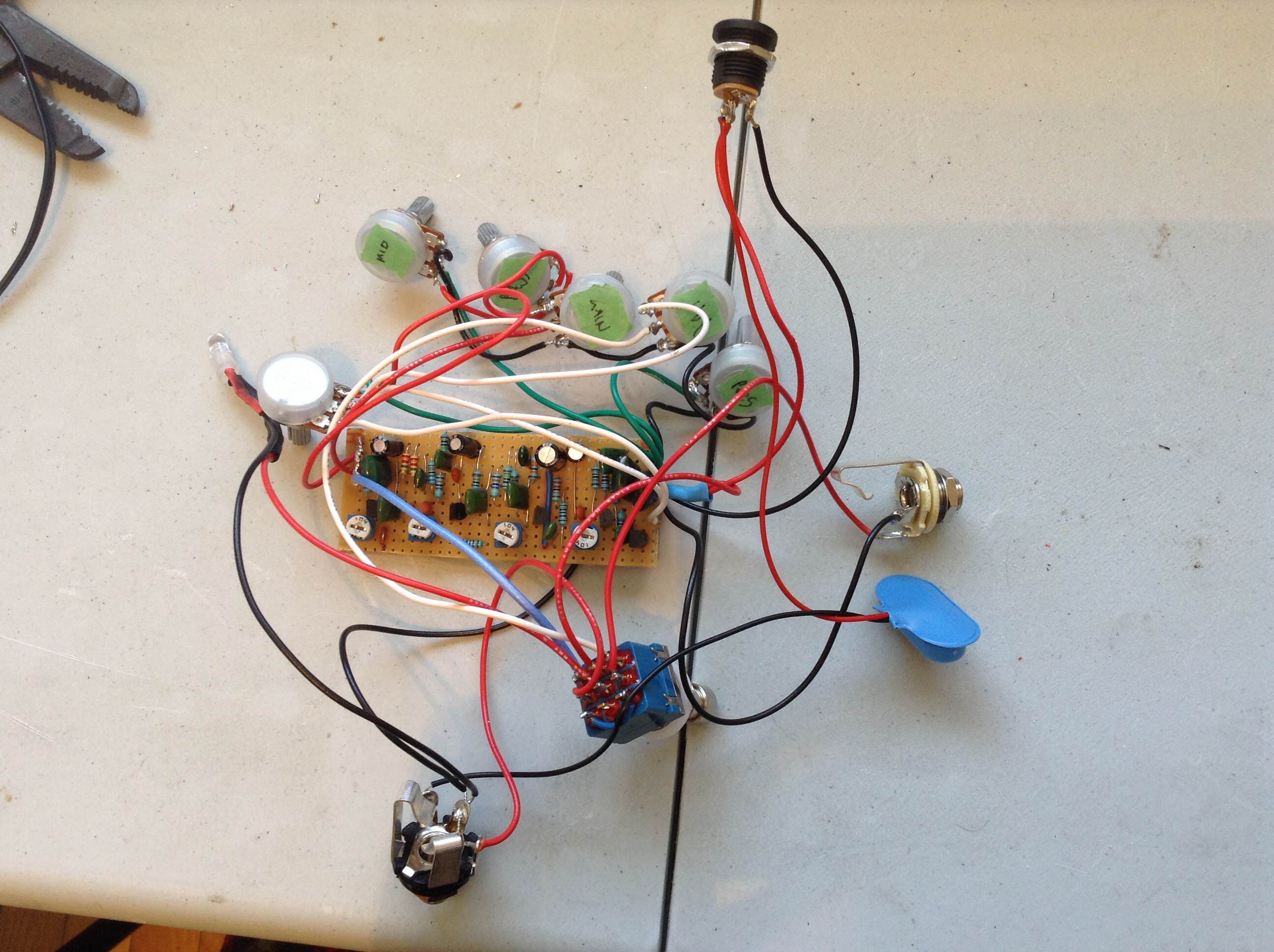 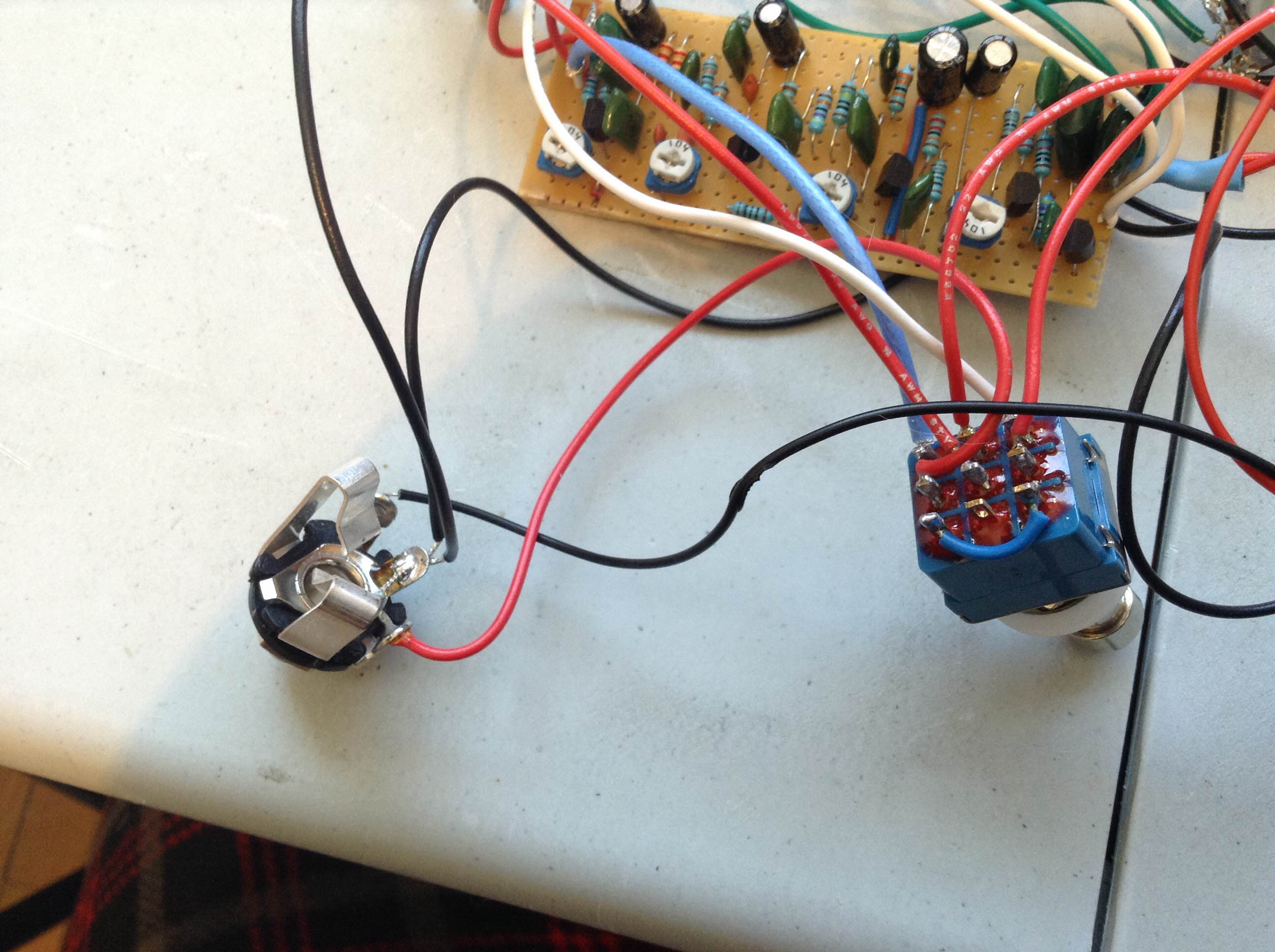 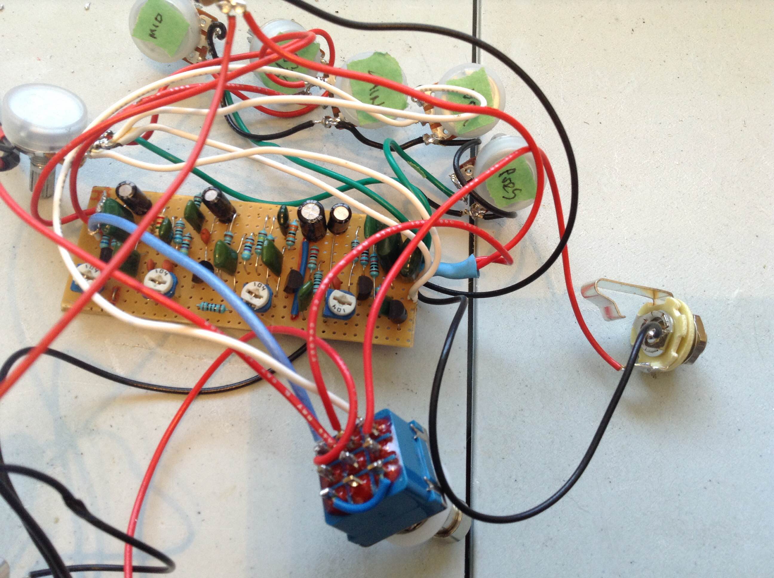 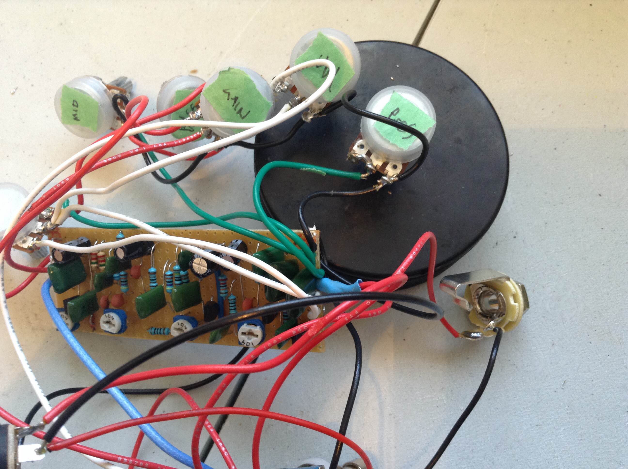 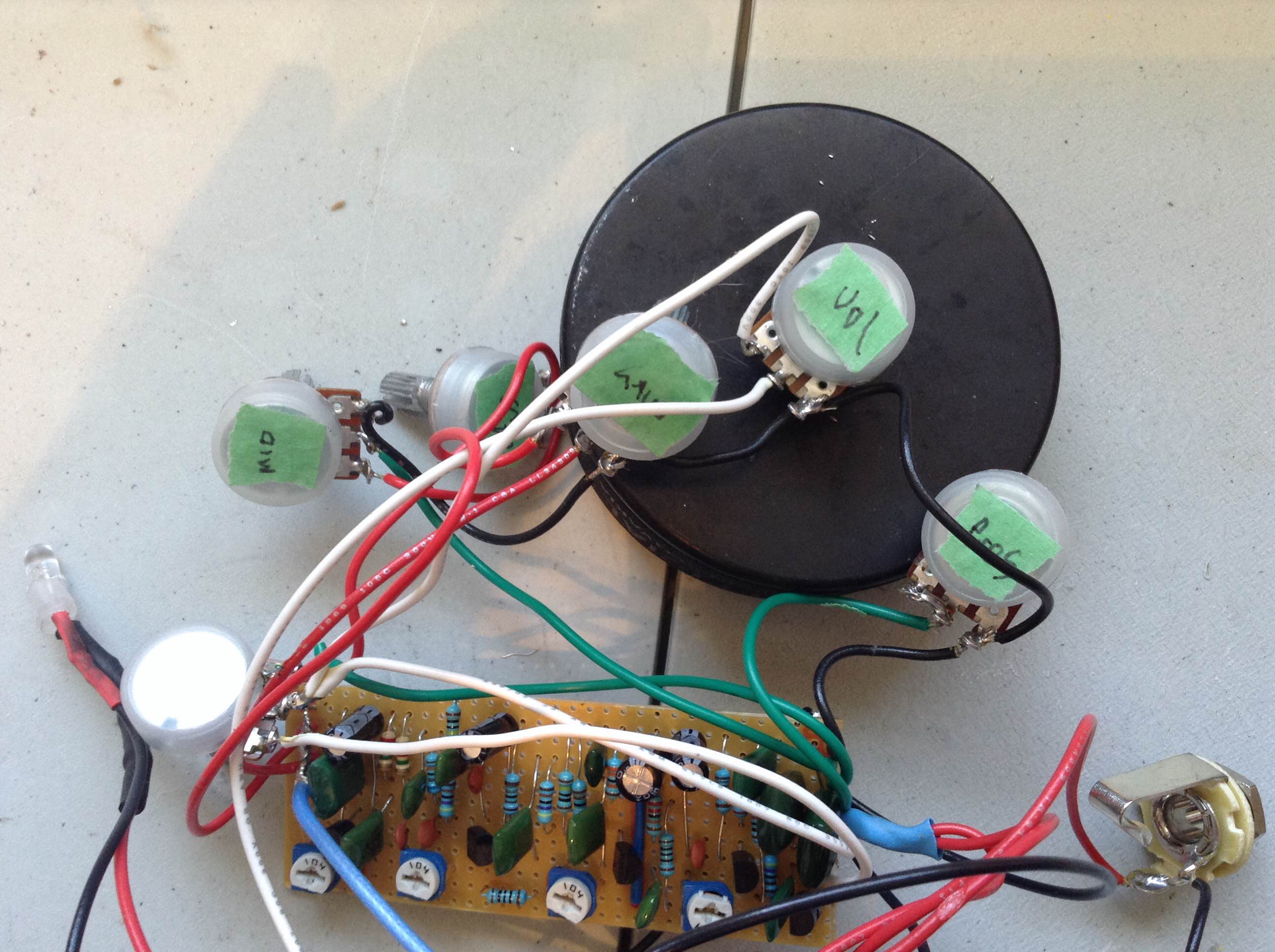 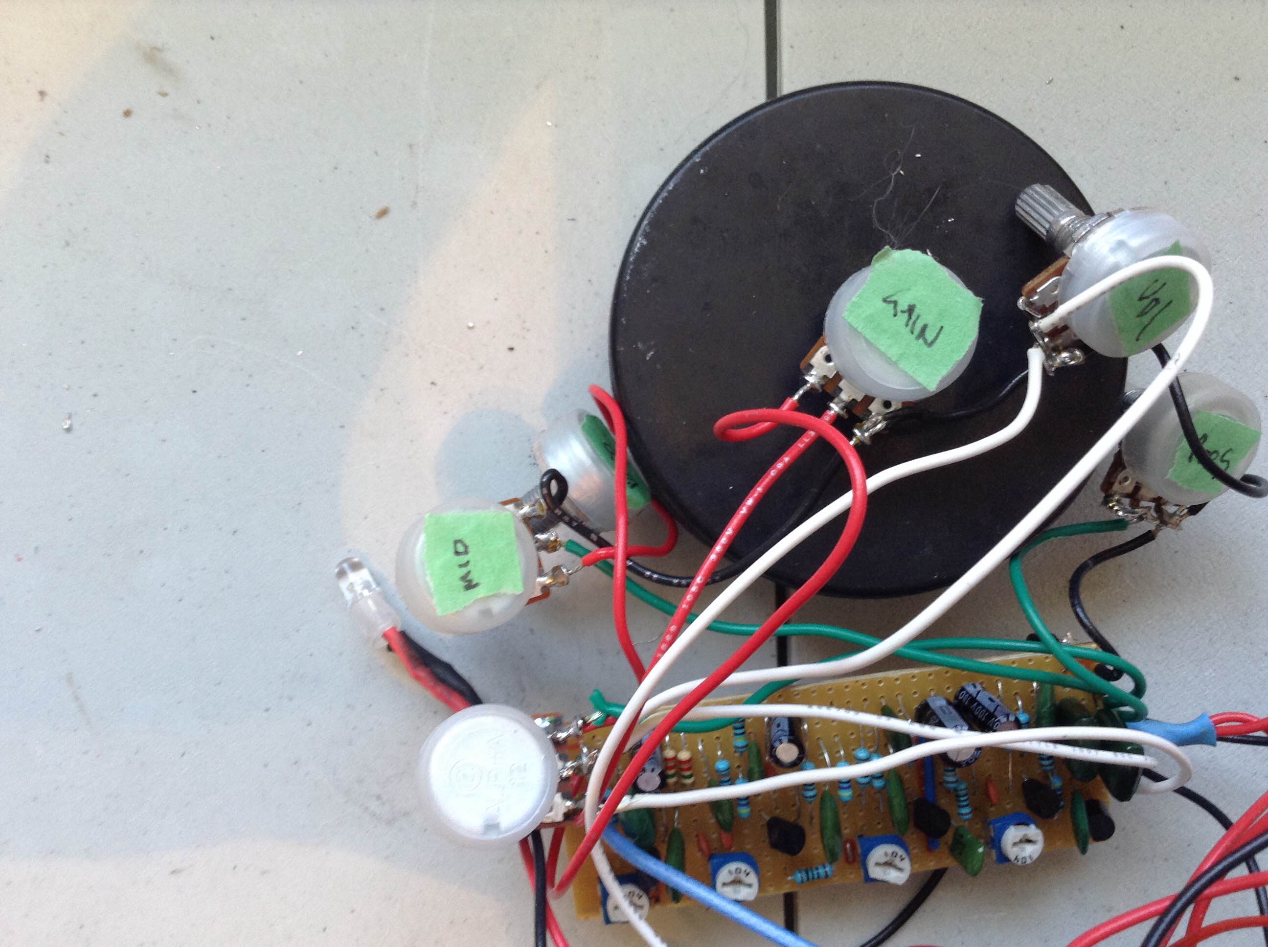 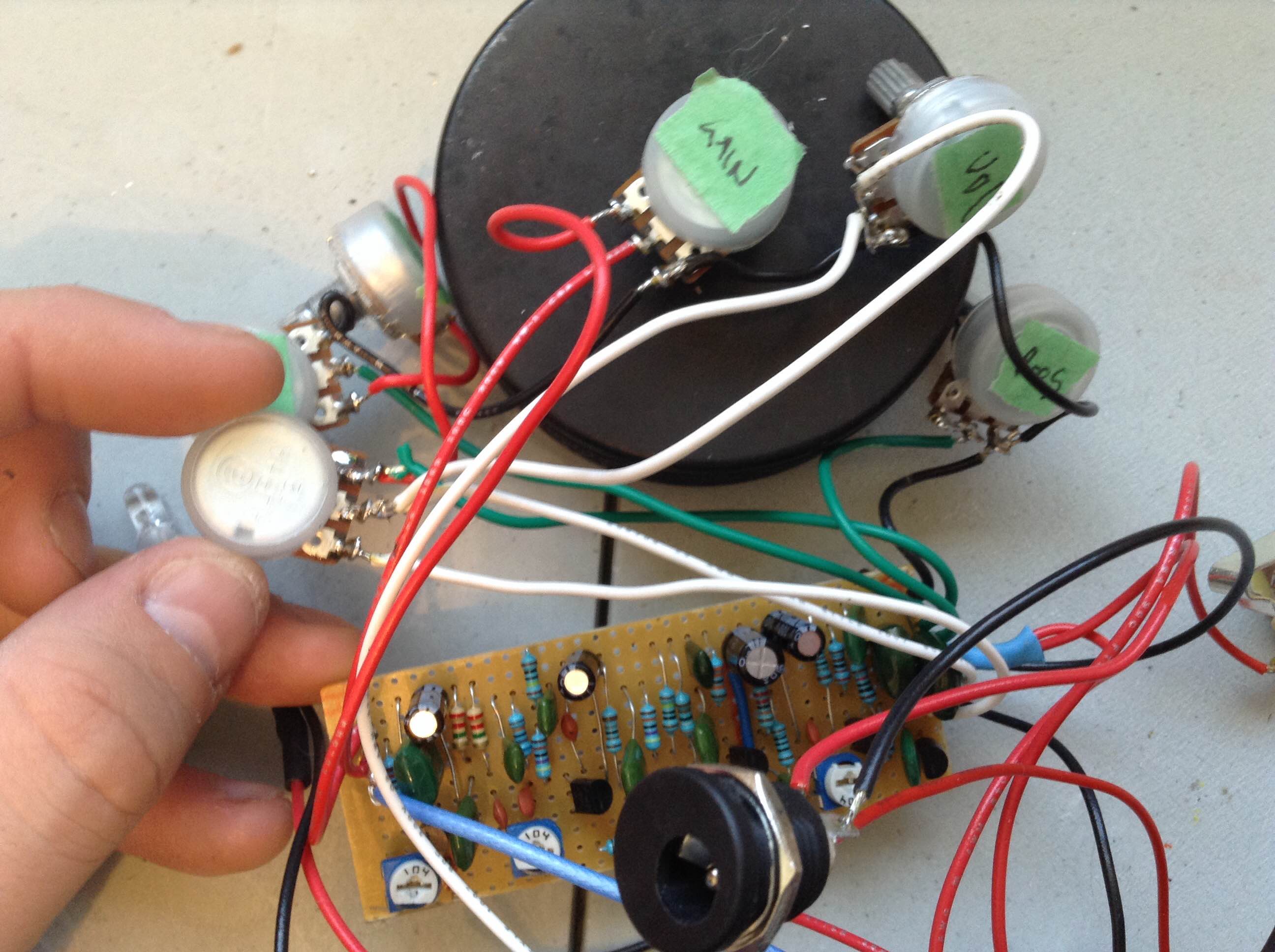 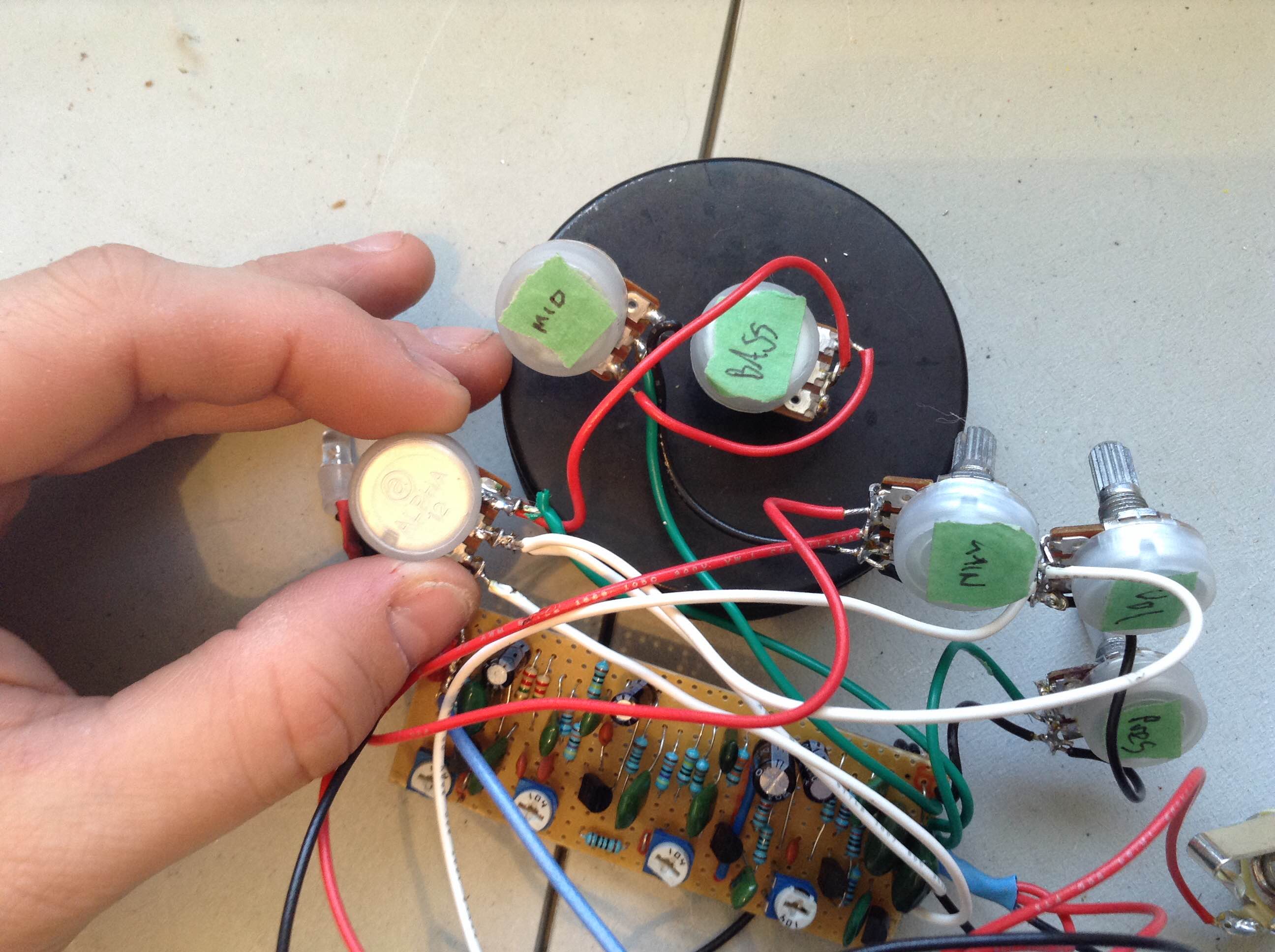 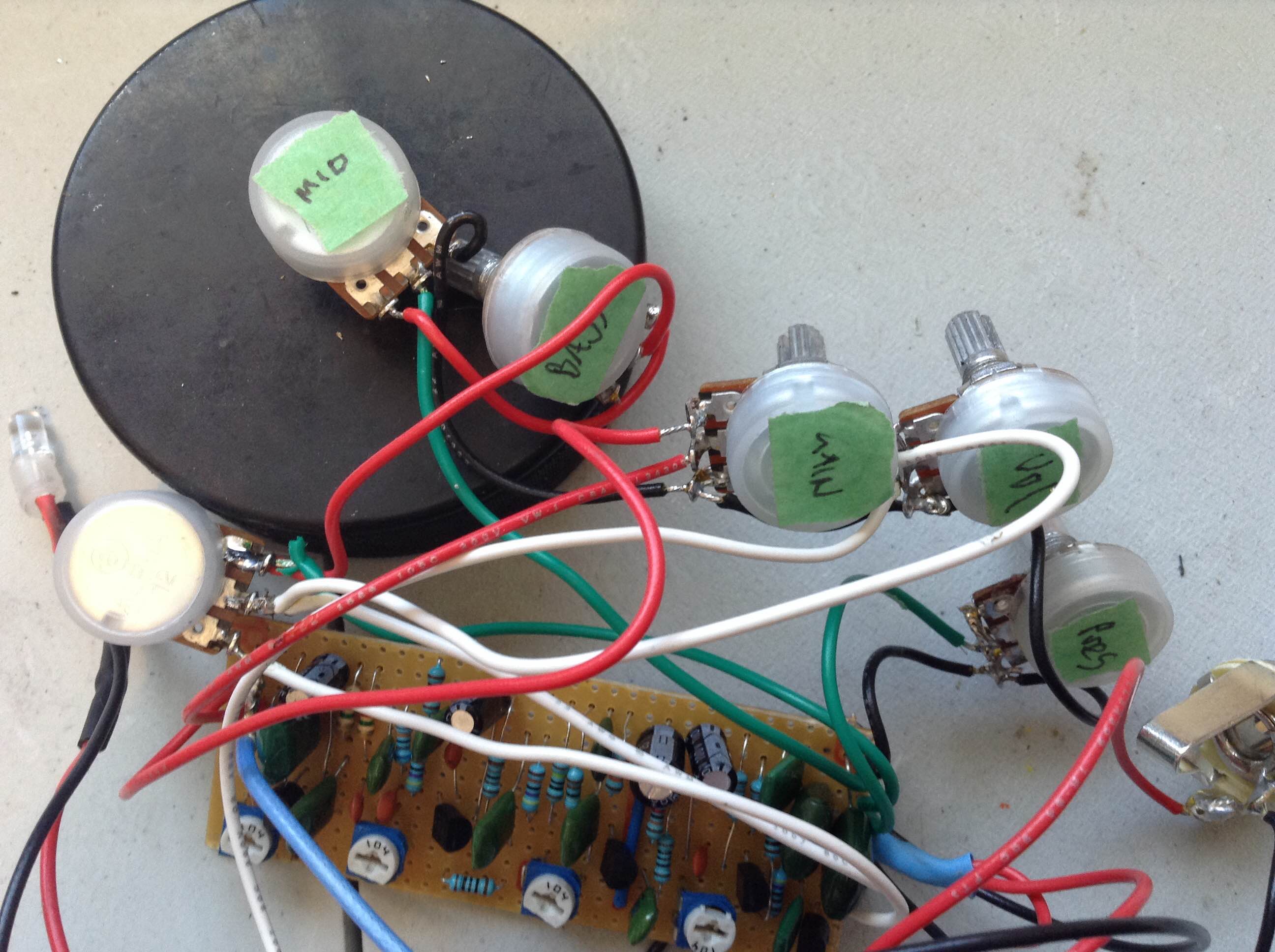 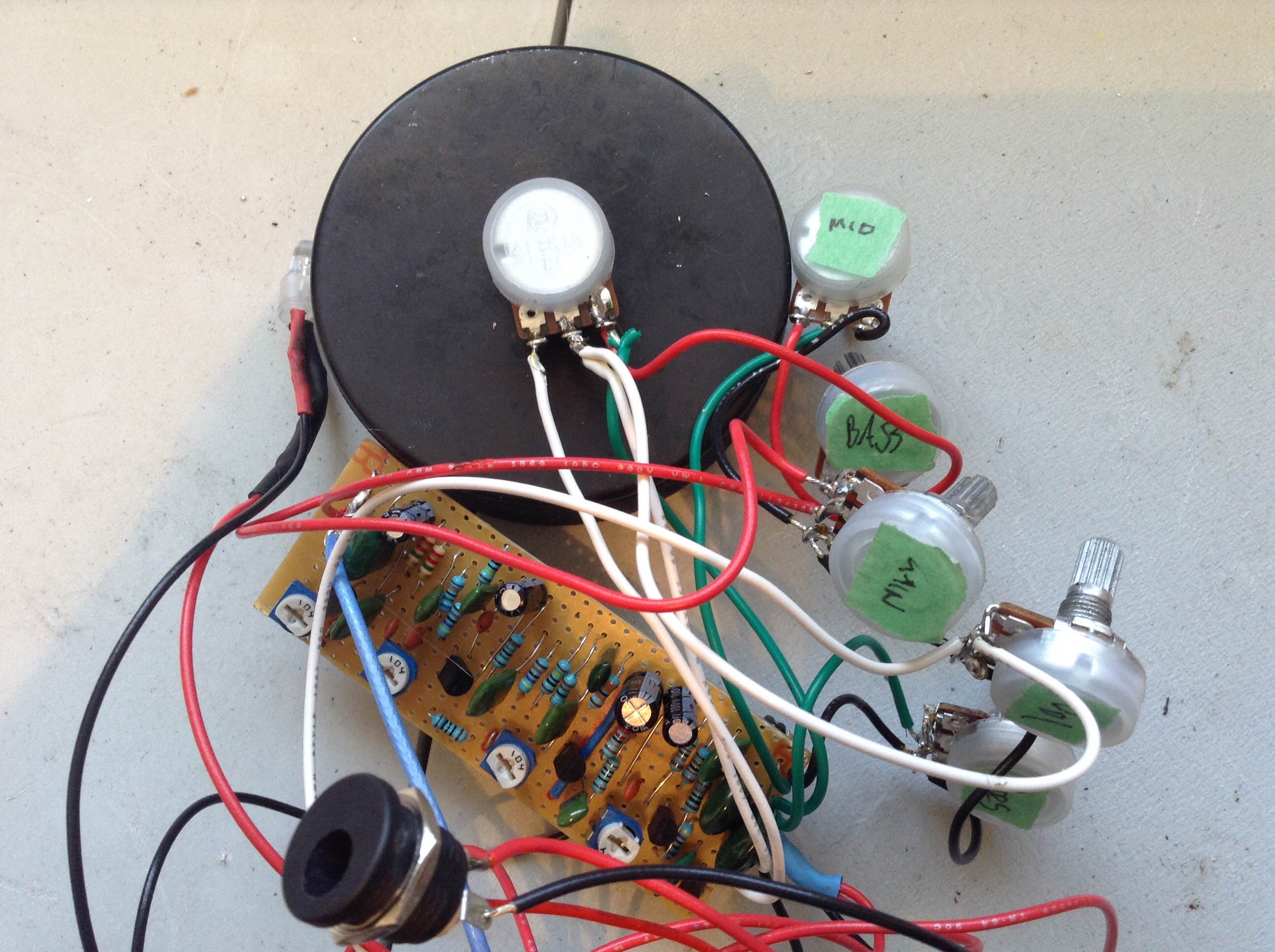 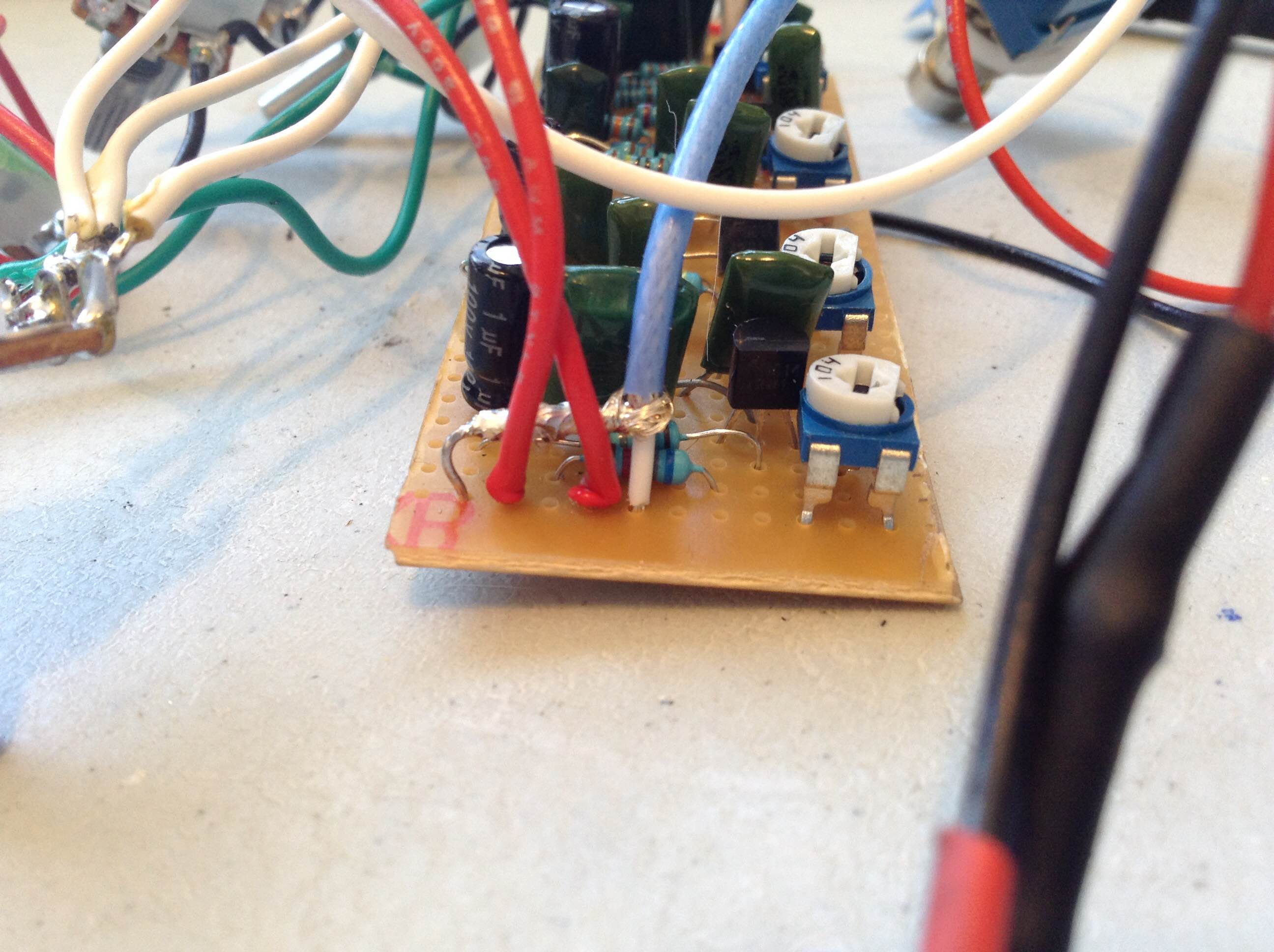 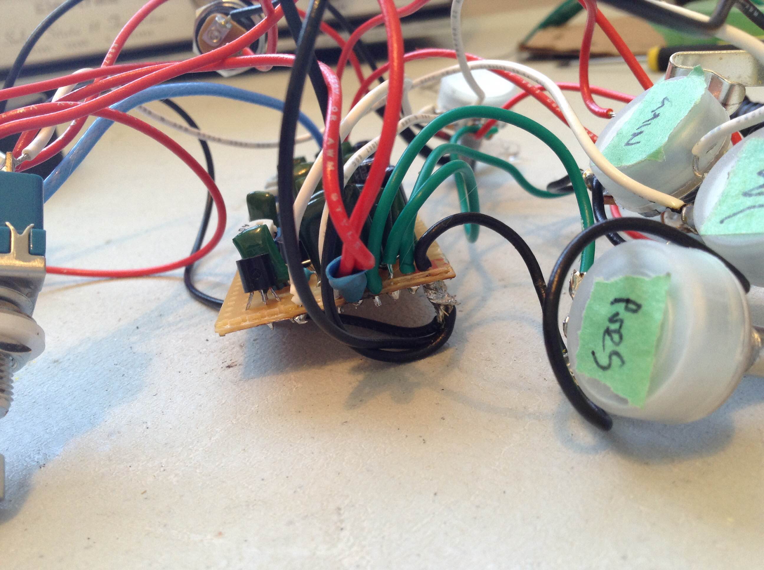 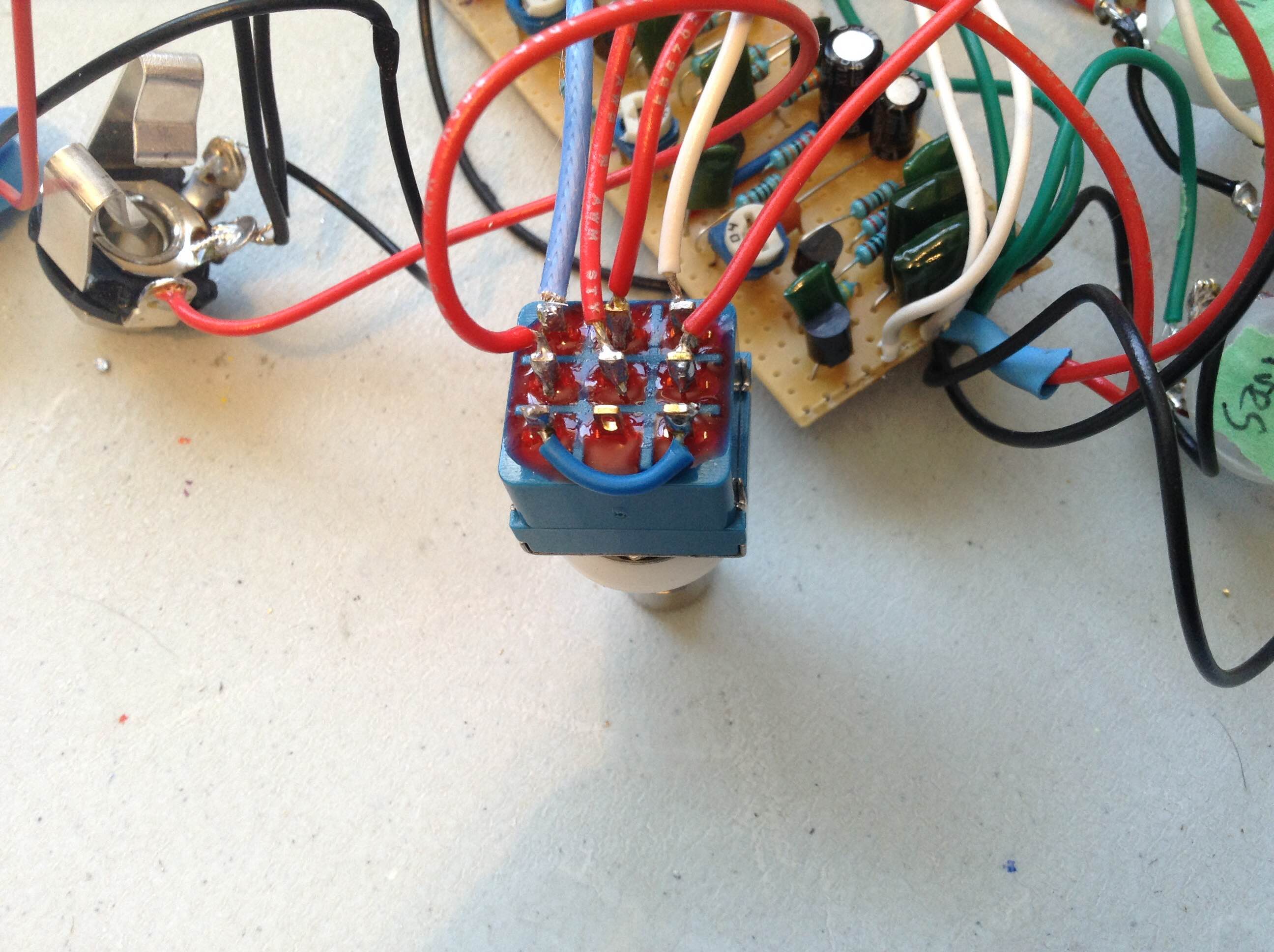 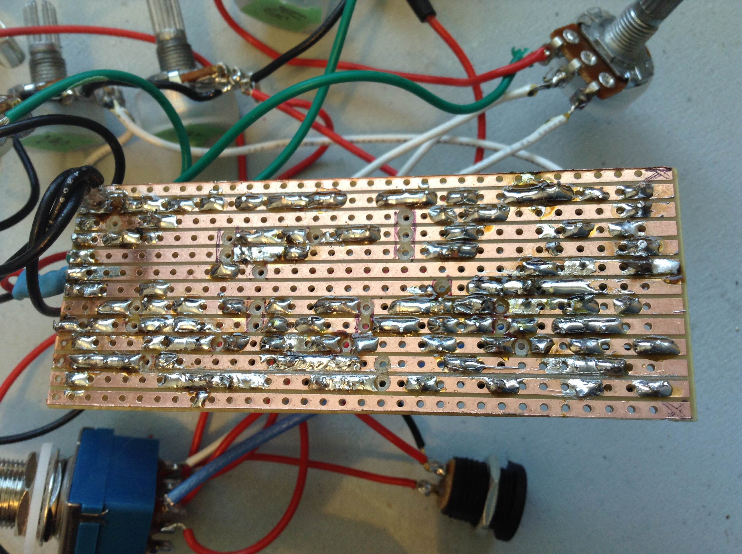 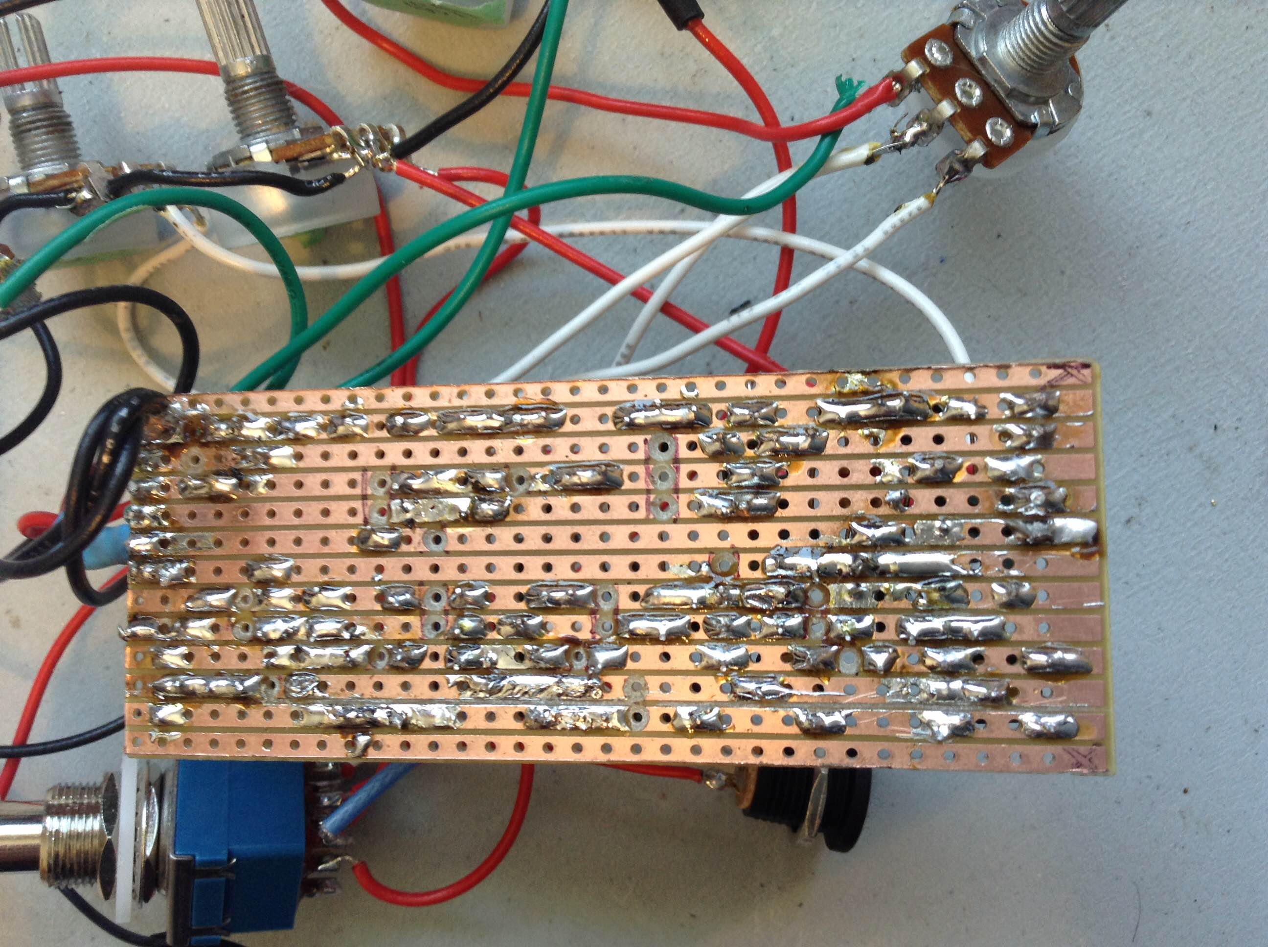 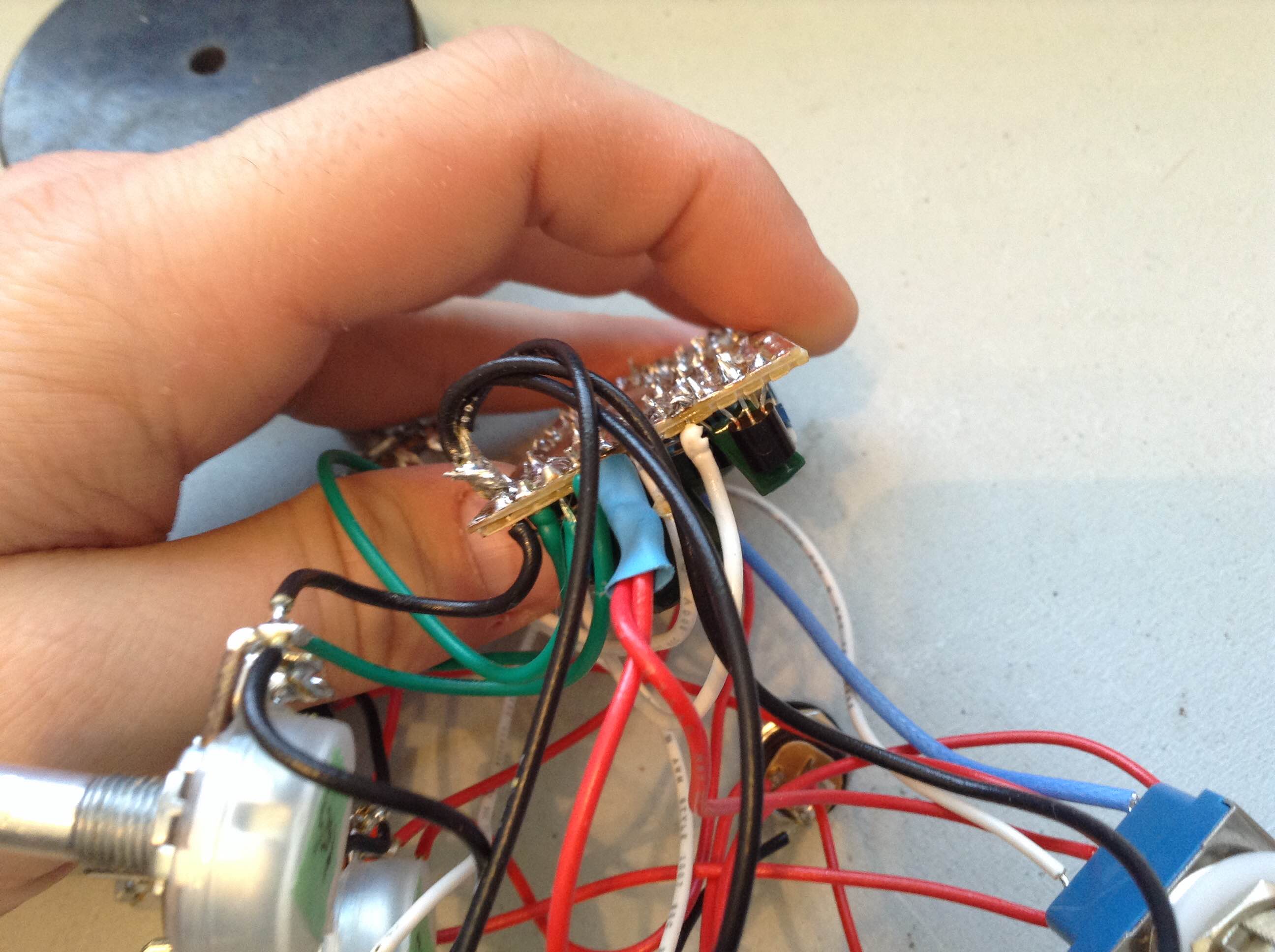
|
|
|
Your input jack tip/ring connections are backwards. They should be like this:
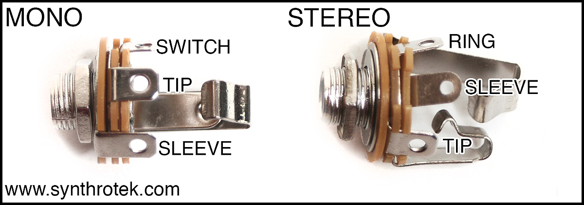 Switch those and you should at least get a bypass signal. |
|
|
switched the leads around, still no signal, even on bypass.
I notice that your image of your mono jack, has a switch lug... could this be the issue? Attached are close ups of the newly wired in and out jacks. 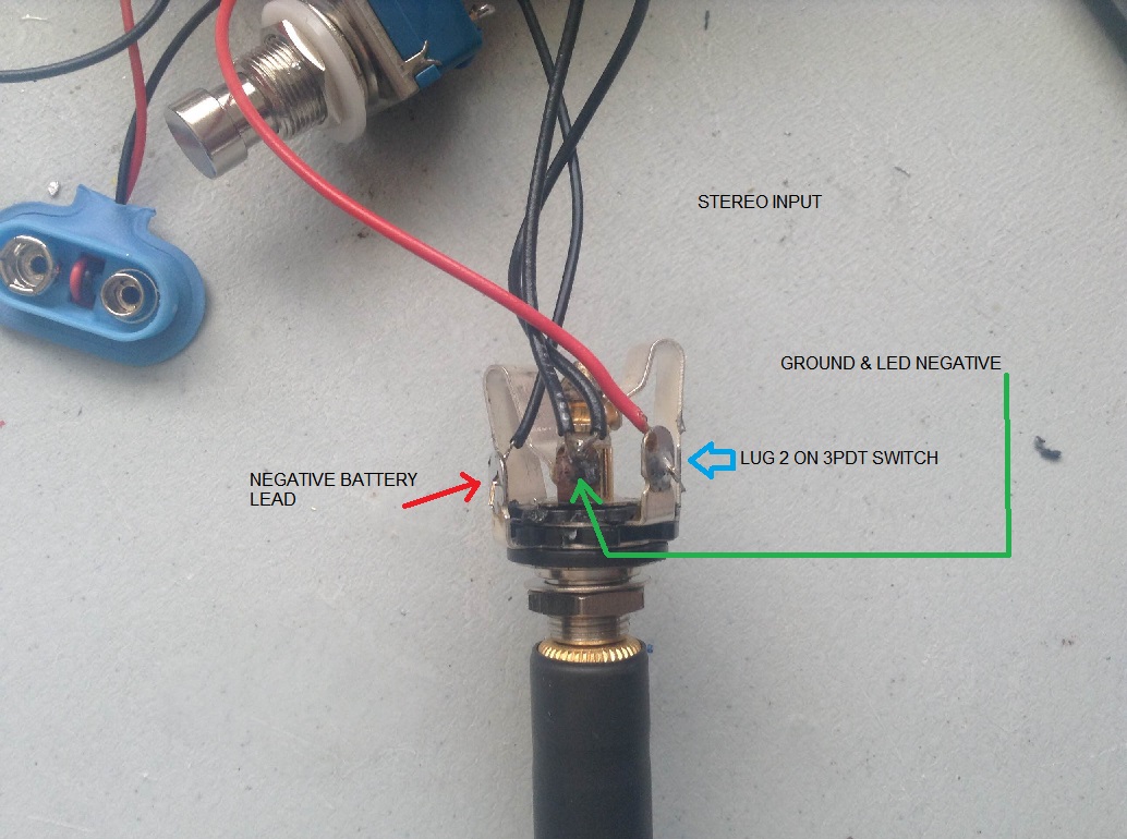 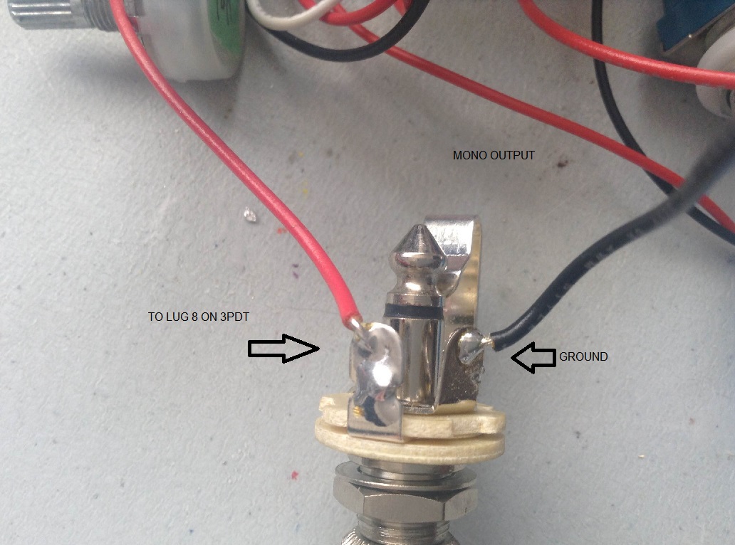
|
|
|
Actually, switch them back. Your stereo jack looks backwards from the image I linked to. In any case, you can trace your signal from the cord to the input jack, the switch, and the output jack and cord with your DVM. There must be a break somewhere. Can't be on any further help until you find the break. Once you can get the signal into the board, then you can debug the board. Good luck!
|
|
|
Ok, switched them back. I have included a picture to indicate where ai am getting continuity, with the effect engaged, and disengaged. So I have my signal into the board. What would be the next debugging step at this point? Again, thank you for all the help, it is greatly appreciated. On Fri, Feb 13, 2015 at 11:54 PM, Frank_NH [via Guitar FX Layouts] <[hidden email]> wrote: Actually, switch them back. You stereo jack looks backwards from the image I linked to. In any case, you can trace your signal from the cord to the input jack, the switch, and the output jack and cord with your DVM. There must be a break somewhere. Can't be on any further help until you find the break. Once you can get the signal into the board, then you can debug the board. Good luck! |

|
|
OK. Let's summarize before proceeding:
(1) When you are in bypass, are you getting a clean guitar signal to your amp? If not, then keep working on that, but it looks like you do have that solved. (2) When you engage the effect there is no sound? There is something obviously wrong there and I would use your audio probe to see where the signal cuts out. The other thing that I can do from afar is to look at your pictures and see if I spot anything amiss with your build versus the layout. If it looks like the layout is OK, then I would suggest reflowing all solder joints to make sure you don't have a cold solder joint somewhere. That can cause a break even though the solder joint looks OK. You're getting voltages on all of your transistors to that's good - means you're getting power to the circuit. Let us know what you find out as you proceed. |
|
|
(1) When you are in bypass, are you getting a clean guitar signal to your amp? Yes, in bypass, I am getting a guitar signal. (2) When you engage the effect there is no sound? Correct, no sound comes out (knobs are set to 12 O'clock) I am still getting voltage to my JFETs after relowing the solder. Again, thank you On Sun, Feb 15, 2015 at 1:40 PM, Frank_NH [via Guitar FX Layouts] <[hidden email]> wrote: OK. Let's summarize before proceeding: |
|
|
I looked at your figure - that's an odd place to lose the signal.
OK. Try this. Use your audio probe to examine the Gate and Drain of each JFET. You should get a clean signal at the Gate of Q1. The drain of Q1 should show and boost as its signal has been boosted by the JFET. As you go to Q2, Q3, ... the signal should get more overdriven. If you lose the signal at the first JFET look for a solder bridge or break in the signal. What can happen is a solder bridge connects your signal to ground and your signal is then lost. See what you can find. Go component to component. It takes time but you should find it. Good luck. |
«
Return to Requests
|
1 view|%1 views
| Free forum by Nabble | Edit this page |