Dr. Scientist Woofer Wailer
|
I have the schematic for this pedal and I'm dying to build one. May I request a layout for it?
Schematic |
|
Great find, MatSmith!
This is a great pedal. My schem>vero chops aren't where most others' here are, but later tonight I'll start the process and post back with results if a savant beats me to the punch, which is pretty likely. Just a quick note, as I'm sure you're aware, Dr. Scientist makes amazing effects and Ryan @ Dr.S is such a good guy... definitely a builder to support by buying his effects if you have the means. Anyway, great find. Did you draw this schem yourself? I wasn't aware of any verified Dr.S schems on the internet. |
|
It's a tubescreamer with switchable input cap, and combined clipping diode combo/gain frequency range switch. It would.be fairly easy to adapt a stock tubescreamer vero to have these mods.
|
|
In reply to this post by notnews
You're right. Ryan at Dr. S is a super great guy.
I have to admit, I didn't find this schematic. I contacted Ryan and he sent it to me. Major dude! |
|
In reply to this post by MatSmith
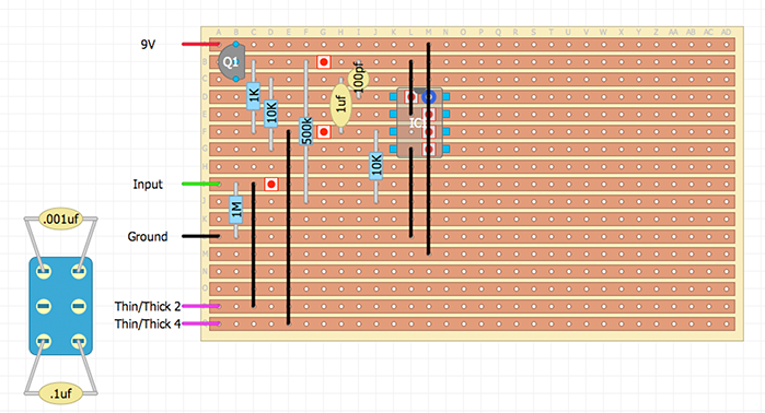
Tried to have a go at this. I've never translated any schematic into vero before so I've been using the TS808 vero layout and trying to adapt it to match the modifications.
Am I close for a starter? 
|
Re: Dr. Scientist Woofer Wailer
|
You're definitely on the right track.
I'm by no means a master layout designer like a few folks here but I think I can offer a few tips... 1. I tend to do the power supply first. This gives me a solid idea where 9V, GND and Vref will be. These are likely to be your most used connections so it allows me to plan ahead regarding ICs, transistors, GND links etc. You have no Vref which is why you currently have resistors going nowhere. 2a. Always keep a mind of the physical real world size of the components you're using. By that I mean try to leave space for bulky items like high value electro caps. They may look fine right next to each other on a layout but really struggle to sit beside each other on the vero. 2b. The opposite could be said about smaller components. You placed your 100pf cap between pin 1 and pin 2 but you've used a link. While this is perfectly fine electronically...you've made unnecessary work for yourself during the build. That 100pf can physically connect to pins 1 and 2 directly, saving yourself a link. 3. Remember that every node you see on the schematic should equal a connection on the layout. You have drawn the switch so that the input goes through either the 1n cap or the 100n. Again this is fine but thats not what the schematic tells you. The 1n cap is ALWAYS in the circuit and the 100n is switched in in parallel. You could easily sort this out by linking the middle row on the switch with the top row. Instead of modifying an existing layout...maybe you should try drawing your own. You'd probably learn more, especially when it comes to schematics. After doing it for awhile you'll soon see where you can do your own mods on schematics and then translate it to vero. Good luck |
|
This post was updated on .
Hey Ciaran. Thanks for all the kind comments. I appreciate it!
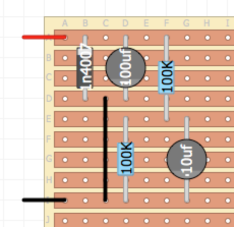
Maybe I will start again off my own steam. I have a question. On the schematic the power supply stuff has a "x2" in brackets. Can't quite work out what this actually means? Any ideas? EDIT: Just started again and began with the Power section like you suggested. I've got this...  Does that look about right? Vref would be row E, if I'm correct? Still need to work out what that x2 bit means... |
Re: Dr. Scientist Woofer Wailer
|
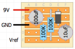
Thats looks all good. I'm not sure what the x2 refers to...maybe 2 10uf filter caps on Vref?
Have a look at this below. By having my vref resistors "overlap," it allowed me to move my ground closer to the 9V rail. This not only allowed me to span the 100uf appropriately but also removed a link and compacted the whole area. Again, we all do things differently. This is just how I would approach it. 
|
«
Return to Requests
|
1 view|%1 views
| Free forum by Nabble | Edit this page |

