Dr Zia Carmen Ghia Emulator

classic Classic list List threaded Threaded
16 messages Options
Reply | Threaded
Open this post in threaded view
|

Dr Zia Carmen Ghia Emulator

Rock Glenn
This post was updated on .
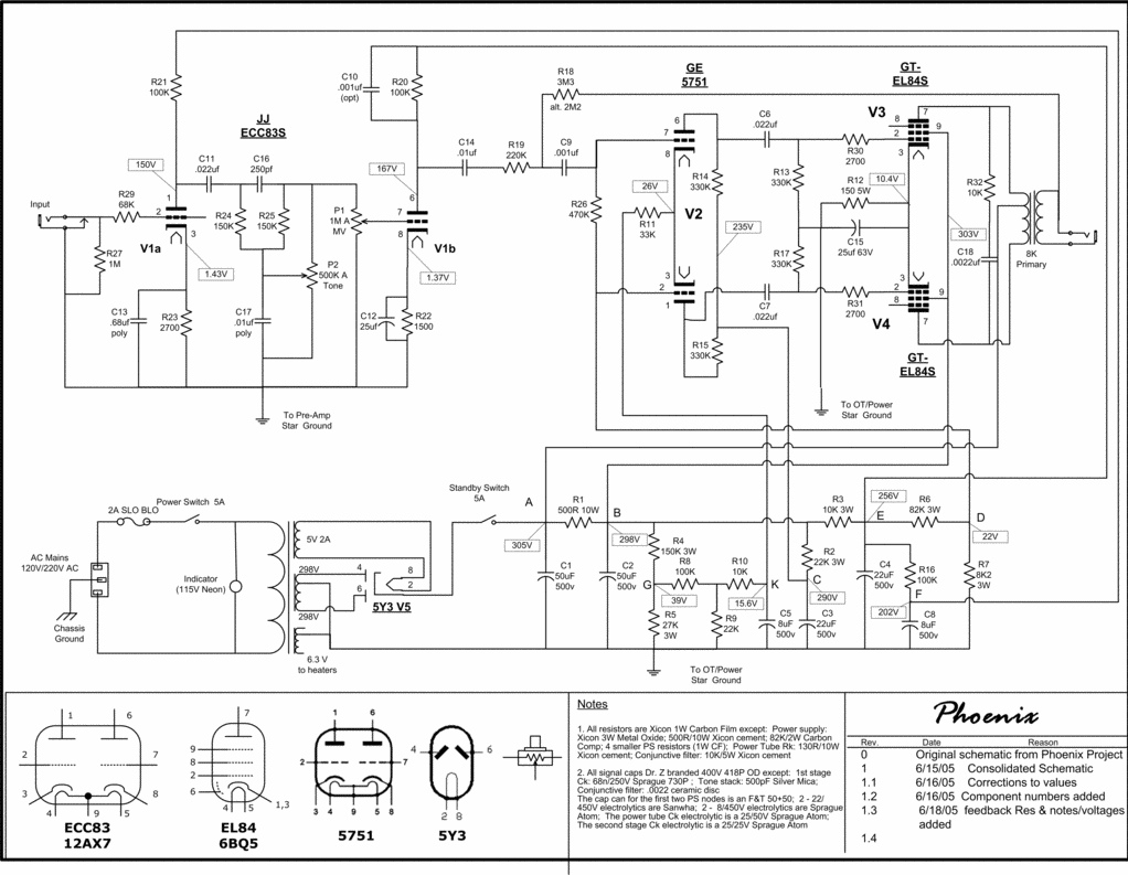
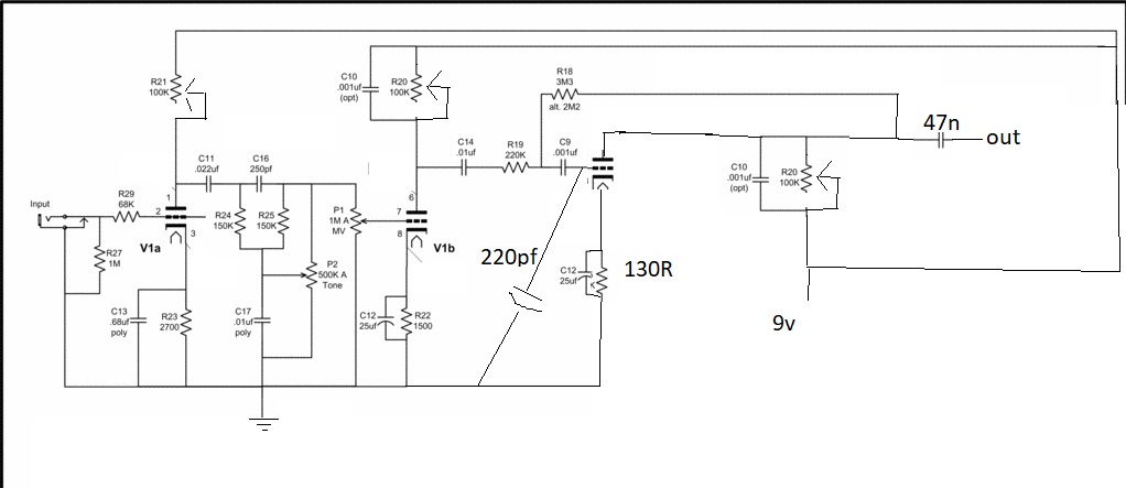
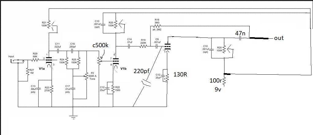
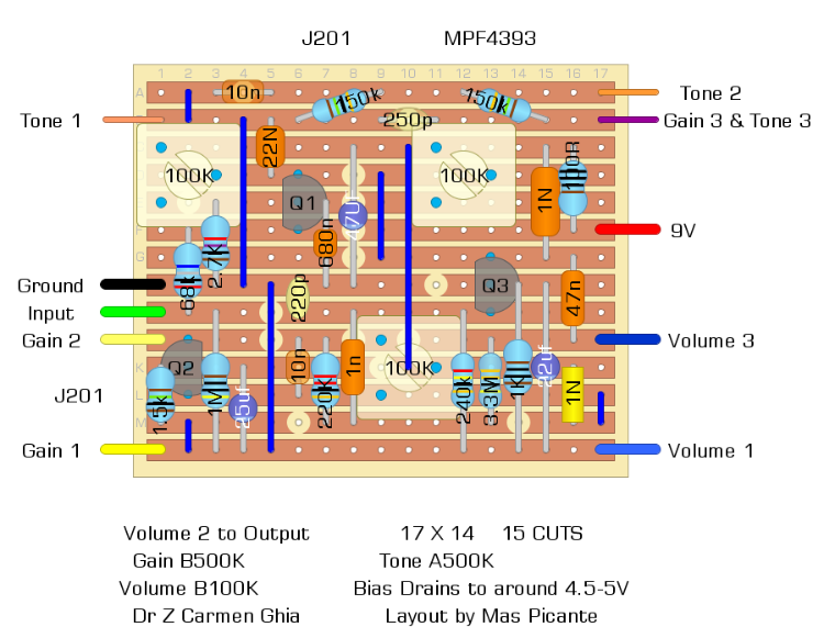
I've been drawing amp emulators from schematics lately, and this one has me stuck. Q1 and Q2 bias normally. If I bypass Q3 it sounds great, but too clean. I designed it so Q3 acts like a single ended power tube.

I can't get any type of JFET to bias right in Q3. They either read 9V on the drain, or the voltage slowly tapers down to zero. I've tried removing the 1n cap on drain and the 22uF cap on the gate. I've tried every resistor between 130R and 560R, I removed the trim pot and tried resistors. It still does the same thing no matter what.

When counting cuts, I missed one so ignore that. And I used an insulated jumper, so it's not touching the Q1 trimpot.

Anything jump out at anyone, why can't I get Q3 to bias?

EDIT: Layout Updated with 240K resistor added Gate to Ground on Q3, not verified yet

EDIT #2 verified, layout Updated giving the 240K resistor more space, Gain pot changed to B instead of C taper because I only did a reverse log because I had more of them on hand. The Tone pot might be backwards, but it's a weird tone circuit so It's hard to tell how it's supposed to be oriented.

www.reverberation.com/rockglenn
Reply | Threaded
Open this post in threaded view
|

Re: Dr Zia Carmen Ghia Emulator

induction
Got a schematic?
Reply | Threaded
Open this post in threaded view
|

Re: Dr Zia Carmen Ghia Emulator

Rock Glenn


I used this from Revolution Deux
www.reverberation.com/rockglenn
Reply | Threaded
Open this post in threaded view
|

Re: Dr Zia Carmen Ghia Emulator

induction
Did you make any other changes besides replacing the tubes with jfets?
Reply | Threaded
Open this post in threaded view
|

Re: Dr Zia Carmen Ghia Emulator

Rock Glenn
I added the 220pf on the gate of Q3 and the 1nf to the drains of Q1 and Q3, but technically I only used the Dr Z schem up to the capacitor feeding the Gate of Q3, then it's a simple Jfet boost that I based of the Dr Z mini-Z. For some reason it's like the Ghia preamp schematic and the "single-ended" Mini Z power section aren't compatible and I don't know why.

I also added the 47nF output cap.
www.reverberation.com/rockglenn
Reply | Threaded
Open this post in threaded view
|

Re: Dr Zia Carmen Ghia Emulator

induction
It will be much easier for us to help if you can upload a schematic of what you actually built. Do you have one you can post?

The layout doesn't convey the electronic operation of the circuit the way a schematic does, and trying to make mental substitutions on a different but similar schematic means we will probably miss something. Also, there could be a simple build error that's causing a problem, which we probably won't find unless we compare the layout to the actual schematic.

We'd love to help, but you have to make it a little easier on us.
Reply | Threaded
Open this post in threaded view
|

Re: Dr Zia Carmen Ghia Emulator

Rock Glenn
Gotcha, that makes sense.

I almost tossed this one away, but it sounds too good when the bias is set for a split second.

Do you know if there is a way to export a schematic in the DIY creator software?

If not I can draw it by hand I suppose.
www.reverberation.com/rockglenn
Reply | Threaded
Open this post in threaded view
|

Re: Dr Zia Carmen Ghia Emulator

induction
I've never used diylc for a schematic, so I'm not sure if it's possible. I usually use LTSpice for schematics. I know there are also online schematic sites where you can easily drag and drop. Here's one. There are plenty of others, if you don't like that one. (I haven't tried it beyond a simple test just now.)

But hand-drawn is just fine also.
Reply | Threaded
Open this post in threaded view
|

Re: Dr Zia Carmen Ghia Emulator

Rock Glenn
I threw this together quickly, but should suffice
www.reverberation.com/rockglenn
Reply | Threaded
Open this post in threaded view
|

Re: Dr Zia Carmen Ghia Emulator

Rock Glenn
One mistake, the negative feedback resistor 3.3M should be on the other side of the output cap
www.reverberation.com/rockglenn
Reply | Threaded
Open this post in threaded view
|

Re: Dr Zia Carmen Ghia Emulator

Rock Glenn
REvised schematic

www.reverberation.com/rockglenn
Reply | Threaded
Open this post in threaded view
|

Re: Dr Zia Carmen Ghia Emulator

induction
Try swapping out the 130R for 1k just to test whether the bias stabilizes.

Also, can you post front and back shots of the board?
Reply | Threaded
Open this post in threaded view
|

Re: Dr Zia Carmen Ghia Emulator

Rock Glenn
I can post pics, but right now the Q3 trimmer was replaced by sockets for a resistor. And the bypass caps are gone. I've built the board up twice with same results.

I tried up to 560 ohm on the "cathode" I'll play with larger values later when I get out of work.
www.reverberation.com/rockglenn
Reply | Threaded
Open this post in threaded view
|

Re: Dr Zia Carmen Ghia Emulator

Rock Glenn
I was able to bias it with a 1K resistor on the cathode, but I had to use 1K resistor to get it to 4.5V on the drain. Did the same with an 820 ohm on the cathode, 820 ohm on the drain to get to 4.6V or so, and all the way down to 150 ohm/150 ohm.

Doesn't sound good though, there is very little drive and most of the treble disappears. I will probably give up on this one as nothing is jumping out at me. Tried J201, J113, MPF's, 2N5457-8-9, 2N5484-5. Nothing wants to work.

I've metered out both boards, there doesn't seem to be any solder bridges, or cold joints.

The layout/schematic look like they should work to me. so idk.
www.reverberation.com/rockglenn
Reply | Threaded
Open this post in threaded view
|

Re: Dr Zia Carmen Ghia Emulator

induction
I just looked at the schematic again and noticed that Q3 doesn't have a bias resistor at the gate. Try putting 1M between gate and ground. That should fix the bias problems. Sorry I didn't notice this earlier.
Reply | Threaded
Open this post in threaded view
|

Re: Dr Zia Carmen Ghia Emulator

Rock Glenn
lol I can't believe I missed that. I guess over the last week, I've looked at it and just thought the 220K was taking care of it. On the GA-5 and some other circuits I have a 220K from gate to ground, I'll probably play with a value around there and see if I can get it working.

Unfortunately I already broke both boards down for parts, so I'll tackle this soon. When I have time I'll update the layout above in case anyone else wants to build it.

Thanks for the help.
www.reverberation.com/rockglenn