(EDIT: scheme added) Power Supply - help me understand this...

classic Classic list List threaded Threaded
12 messages Options
Reply | Threaded
Open this post in threaded view
|

(EDIT: scheme added) Power Supply - help me understand this...

Kost1978
This post was updated on .
Who's able to understand this little thing I have?

This is the power supply I use for my pedalboard for some years now:


With this little thing I can power up to 12 pedals (9V), the idea is quite easy cause the transformer is external and I guess could be "any" transformer capable of converting the 220V AC from the wall plug to 12/15V DC required. The current is then converted to 9V by this little circuit inside the box:


I'd like to "copy" this thing, maybe on a smallar scale, I guess it could be quite easy somehow, so the obvious question is: is there someone here who's able to "understand" this thing just looking at it?
The part I circled in the last pic is screwed directly to the metallic box cover, so to me it looks like a gorund connection for the board, it's just a bit strange cause it has a "funny shape": could also be a kind of cooling part??? I'm just guessing here, so please be patient...

If someone could help me I can upload (or send) more detailed pics!
Thanks in advance!

Here's another pic of the inside, showing the pedals' power connections:


Reply | Threaded
Open this post in threaded view
|

Re: Power Supply - help me understand this...

GoranP
From what I can tell, it's your run-of-the-mill voltage regulator. Prolly not unlike this one
http://www.taydaelectronics.com/l7809cv-l7809-7809-voltage-regulator-ic-9v-1-5a.html

It's screwed directly to the box because it's using the box as a heatsink.

The rest is probably just filtering (at least the two electrolytes are), circuit protection (diode) and LED resistors. If you make more detailed pictures we can very likely get to the bottom of this.

I'm not sure you can make it significantly smaller, though.

Reply | Threaded
Open this post in threaded view
|

Re: Power Supply - help me understand this...

Kost1978
Hi Goran,
and thanks for the reply.

I guess you're right about the Tayda article, the shape is quite similar from what I have "on board"...
I thought the regulator was the transistor (or what it looks like a transistor...) directly north of the smaller electrolitic you can see in the circuit's pic I posted earlier, but anyway...

Whit "smaller" I meant a power supply for let's say 6 pedals, not the 12 I already have, I didn't mean the board size, sorry for the misunderstanding!

I'll try to get more detailed pic and post it back here, thanks again!
Reply | Threaded
Open this post in threaded view
|

Re: Power Supply - help me understand this...

GoranP
Well there are quite a few applications for a voltage regulator, even in the app notes, and some include bjt-s

http://www.fairchildsemi.com/ds/LM/LM7809.pdf

What transistor is it, are there markings on it?

If you want to scale down, just put in less outputs.  The Tayda one is rated at 1.5A, no risk in having some headroom currentwise. Depending on your projected power consumption, you may even get by without using a heatsink (or just a small one and not having to use the enclosure to cool down your regulator). Thermal paste also helps (the kind you put on PC processors), it seems from your pics that there was indeed some paste there.

Reply | Threaded
Open this post in threaded view
|

Re: Power Supply - help me understand this...

GoranP

For example, here's one usage of transistors after a voltage regulator (ignore the transformer and rectifier bit):

http://www.circuitstoday.com/12v-15a-voltage-regulator
Reply | Threaded
Open this post in threaded view
|

Re: Power Supply - help me understand this...

Kost1978
In reply to this post by GoranP
GoranP wrote
 If you make more detailed pictures we can very likely get to the bottom of this
Got some more pics:
Power006.jpg
Power007.jpg
Power012.jpg
Power008.jpg
Power009.jpg
Power011.jpg

I even came up with a sort of "tracing" of the board (sorry if I'm using wrong terms here, but it's really the very first time I do something like this...), I tried to follow all the soldering visibile and draw the various connections, does this make sense? Will it be possible to get this scheme on vero somehow??


Thanks!

PS: by the way, these are the parts I could identify:
1xElectrolitic 220uf 35V;
1xElectrolitic 47uf 35V;
2xCapacitor? Yellow rounded thing, on surface is written "104";
1xTransistor? On surface is written C546B W87 (see pic 011), could be this one:
http://www.taydaelectronics.com/bc546-transistor-npn-65v-0-1a-to-92-bc546b-126.html
1xDiod? On surface I can read the partial writing, 1XN4...
Reply | Threaded
Open this post in threaded view
|

Re: Power Supply - help me understand this...

GoranP

I tried coming up with a schematic from your pictures but have failed to turn up with anything satisfactory. Just too many unknowns. Since you have one in your hands, I'm assuming your tracing is correct as it is in no way complex.

What I can tell you:
- the transistor is indeed the one you found, a BC546B
- the diode (probably any of the 1n4000 family will do) across the regulator serves as a reverse current protection if you shortcircuit your input
- 104 denotes a 100nF capacitor, any non-polarized version and is there for stabilization (as are the two electrolytes)

Reply | Threaded
Open this post in threaded view
|

Re: Power Supply - help me understand this...

Kost1978
Hi Goran
thanks a lot for the effort and for identifing for me the missing components.

I'll try to draw a stripboard scheme myself, even if I've never done this before, just to see if I somehow understood the logic behind this beautiful "sport".

I'll get back if I ccome up with something!
Thanks again!
Reply | Threaded
Open this post in threaded view
|

Re: Power Supply - help me understand this...

Kost1978
Does this at least make sense?


The following is a side-by-side comparison of both side of the board, paired with the schematic I drew AND the tracing:
Side_By_Side_2.jpg

Thanks.
Reply | Threaded
Open this post in threaded view
|

Re: Power Supply - help me understand this...

Kost1978
Could someone have a look to my diag and give me some feedbacks please?
Even if it's something like "ok, is a piece of crap, go back to your real job...", at least I'll know I can uninstall "DIY Layout Creator"...
Reply | Threaded
Open this post in threaded view
|

Re: Power Supply - help me understand this...

induction
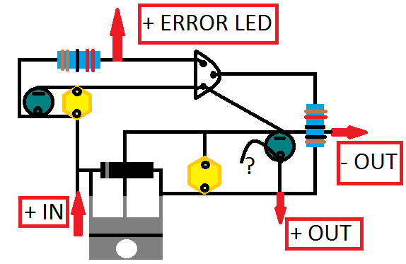
Good job on your first vero layout.

It's hard to tell from the photos, but your trace looks accurate as far as I can tell.  Your vero layout is missing a link between row c and the right side of row d, meaning C1, C2, and Q1 are missing a ground connection.  R1, R2, and D2 should have track cuts underneath them.  The way Q2 is drawn is ambiguous: all legs appear to be connected to row f, when none of them should be (I think I understand what you're doing there, but the drawing is confusing).

A few tips:
Usually a vero layout will not have the components arranged the same way as a pcb layout.  Use the vero strips to your advantage instead of trying to replicate the pcb.  This makes errors easier to troubleshoot.

You should also avoid components touching or crossing.  For example, C1 and C2 are probably too close together to fit on the board without touching, and D2 crosses a jumper, and won't sit flat against the board.  

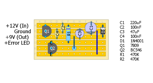
I usually do my layouts with specific components in mind.  I buy parts at a surplus store and the caps come in different shapes and sizes.  I will size them accurately in diylc to make sure everything fits.  Not everyone does this, but I find it helpful.

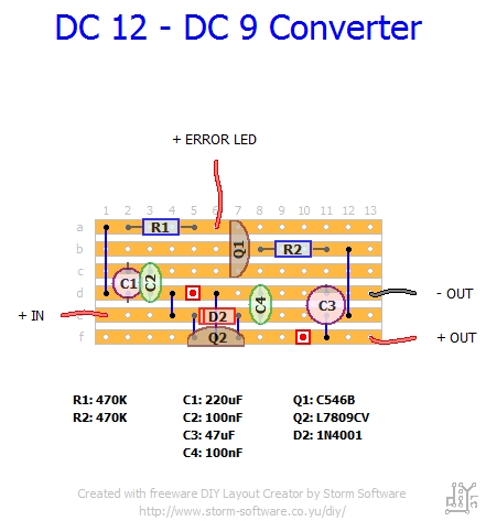
Here is my vero layout of the circuit you drew.  It's roughly the same size as yours, but uses fewer cuts and jumpers.


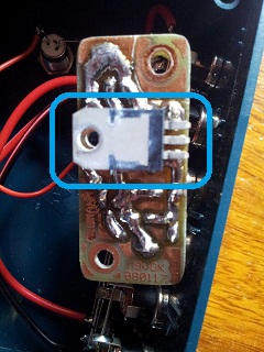
By the way, I think the transistor in this circuit might work as a switch for the error LED, but I can't tell for sure from the pictures.

Good job, and keep it up.  It gets much easier with practice.
Reply | Threaded
Open this post in threaded view
|

Re: Power Supply - help me understand this...

Kost1978
Hi Induction,
sorry for the late reply and thanks a lot for your help!

I knew from the biginning something was "wrong" with my layout, I built 5/6 working pedals from Mark's layouts and I kind of noticed how different they look from the one I drew.
Beeing completely unaware of how a circuit works, I thought it was easier to simply replicate my tracing, actually is hard for me to understand how you came up with your scheme (which for sure look quite "clean" compared to mine) from my tracing!!

I'll probably take my time and see if I can somehow understand how the current pass through my tracing and see if I'm able to match it with your vero, right now I can just thank you again for taking some time to give me some help!

Have a nice day!