EM-Drive

classic Classic list List threaded Threaded
22 messages Options
12
Reply | Threaded
Open this post in threaded view
|

EM-Drive

LettucePrey
This post was updated on .
Complete
Reply | Threaded
Open this post in threaded view
|

Re: EM-Drive

IvIark
Administrator
This will be done about 30 seconds after I get a proper look inside one, or someone who has one sends me the pics.  I agree it's a nice sounding pedal.
Reply | Threaded
Open this post in threaded view
|

Re: EM-Drive

peavey_xxl
In reply to this post by LettucePrey
http://www.extremecircuits.net/2010/05/10000x-with-one-transistor.html  This is a hint I got from a guy who recently built a clone of the EM Drive.  With all the goop I can't tell what kind of transistor it is.  You can only see the green paper in oil caps but can't read anything on them.  Hope this somewhat helps.
Reply | Threaded
Open this post in threaded view
|

Re: EM-Drive

IvIark
Administrator
Thanks for the link
Reply | Threaded
Open this post in threaded view
|

Re: EM-Drive

peavey_xxl
No problem glad I could help even though I'm a noob.  Would it matter if these were 250 k pots?
Reply | Threaded
Open this post in threaded view
|

Re: EM-Drive

IvIark
Administrator
The volume pot together with the 100n cap in front off it make a high pass filter that start cutting low end starting at 16hz.  If you swap it for a 250K pot it will start cutting lows at 6hz.  But both these levels are well below the lowest note on both guitar and bass and so it only attenuates frequencies out of the audio range.  

The Gain control is a pre-effect level control and so just adds resistance in the path to tame the signal.  

Changing to 250K would change the input and output impedance slightly but whether that would cause a noticeable difference to the tone, and if so which one you would work best with any individuals gear I don't know.  It would be a quick thing to test though for anyone who wanted to experiment.
Reply | Threaded
Open this post in threaded view
|

Re: EM-Drive

IvIark
Administrator
In reply to this post by peavey_xxl
Having said all that, if anyone can confirm the pot values I will obviously alter those shown on the layout so it matches.  I couldn't read them on the gutshot I saw and don't expect it to make significant difference and so just went with 100K.
Reply | Threaded
Open this post in threaded view
|

Re: EM-Drive

peavey_xxl
Pot values are 250 K.  I own this pedal.
Reply | Threaded
Open this post in threaded view
|

Re: EM-Drive

IvIark
Administrator
OK cool thanks for letting me know, I'll update the layout
Reply | Threaded
Open this post in threaded view
|

Re: EM-Drive

peavey_xxl
Ok I went for this on my second build at max gain they sound identical.  Now at minimum drive the Em Drive has no grit, whereas the one i built sounds a bit dirty at minimum. What are your thoughts on this?
Reply | Threaded
Open this post in threaded view
|

Re: EM-Drive

Rolf Poti
your components isn't hand picked after the value that is used in the original.
But the biggest reason is probably diffrent Hfe on the transistor. you could try swap transistor to somthing with lower Hfe.
Reply | Threaded
Open this post in threaded view
|

Re: EM-Drive

LettucePrey
In reply to this post by IvIark
I just put this layout together. I used everything the orginal called for: switchcraft jacks, big green mojo caps, cts pots and was hoping to get close to the sound.

I plugged the pedal in....the LED lights up but there is no sound bypassed or on! Is there some sort of troubleshooting to go through when there is no sound at all? This one looked so simple I figured it would be a no brainer. One question...I took the middle lug on the 3pdt to Gain 3 & the top right (looking down at the switch) to Volume 2. Is this correct?
Reply | Threaded
Open this post in threaded view
|

Re: EM-Drive

IvIark
Administrator
You really need to test board before wiring up the switch, you're giving yourself a headache by needing to test two things at the same time to work out which is at fault instead of just one if you tested the board first.

No sound in bypass means the switch must have a problem because that cuts the circuit completely out of the signal path.

How did you wire up the stomp, as per the diagram here?  Can you post a pic of the soldering on the stomp so we can visualise what you've done
Reply | Threaded
Open this post in threaded view
|

Re: EM-Drive

LettucePrey
How do I go about testing the circuit before the stomp is integrated?

I wired the foot switch using the layout here. Here are some pics. I can tell you where each wire is going if needed. The green wires are from the board. The rest are black.

Photobucket Pictures, Images and Photos

Photobucket Pictures, Images and Photos
Reply | Threaded
Open this post in threaded view
|

Re: EM-Drive

peavey_xxl
Can you post a pic of the other side of your board ?  
Reply | Threaded
Open this post in threaded view
|

Re: EM-Drive

IvIark
Administrator
In reply to this post by LettucePrey
LettucePrey wrote
How do I go about testing the circuit before the stomp is integrated?
Just use a terminal block to connect the board input to the input socket, and the board output to the output socket.  Like this:


LettucePrey wrote
I wired the foot switch using the layout here. Here are some pics. I can tell you where each wire is going if needed. The green wires are from the board. The rest are black.
It looks to me that you've got the board input and input socket wires the wrong way round on the stomp.  I can't tell for definite but basing the numbering on this:

1---4---7
2---5---8
3---6---9

Then it looks like you have 4 going up to the Gain pot, and 5 connecting to the socket.  They should be the other way round.
Reply | Threaded
Open this post in threaded view
|

Re: EM-Drive

LettucePrey
Ok I believe I've represented everything how I have it wired. The pictures of the board are the actual one I'm using


Reply | Threaded
Open this post in threaded view
|

Re: EM-Drive

IvIark
Administrator
Yes it was the connection to the gain pot and input socket that wasn't clear in the pic because the green wire was covering the stomp connections, but that looks right as per your diagram.  What transistor did you use and can you post a close up front and back pic of the board?
Reply | Threaded
Open this post in threaded view
|

Re: EM-Drive

LettucePrey
I used a 2N5088 transistor
Reply | Threaded
Open this post in threaded view
|

Re: EM-Drive

IvIark
Administrator
Well there's certainly nothing jumping out at me, but the board could be absolutely fine so we need to find out if that switch is faulty or if you have a dodgy joint which isn't making the required connection.  We know for a fact that something must be wrong with the switch or else you would get a bypass signal.

In this pic is really looks like the "4" wire is going to the "4" lug, and the "5" wire is going to the "5" lug.  
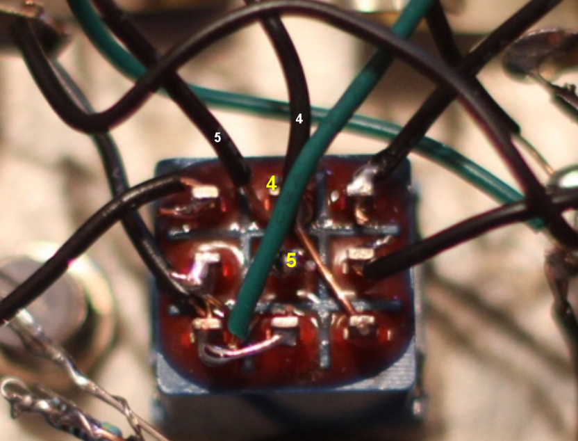


If that definitely not the case?  If it isn't then you must have a problem with your stomp switch, either as far as the internal contacts are concerned, or with a bad joint that isn't performing as intended.  If I were doing this then I'd reflow all the solder on the switch (and sockets) to make sure you have good joints, and if that didn't work I'd cut out the switch so I could prove that the circuit is working and test the switch with a multimeter to confirm a broken contact.
12