Em drive, transistor hFe, help!

classic Classic list List threaded Threaded
8 messages Options
Reply | Threaded
Open this post in threaded view
|

Em drive, transistor hFe, help!

toddvirgil
Hey Guys,

I'm trying to build the EM-drive because I'd like to use it as the basis for a modded circuit. I figured, stupid simple layout, should be a piece of cake right?

I put a 2n5088 in it and it works as expected but sounds like crap compared to the original. The original uses an MPSA18, but when I insert one of those, I get almost no signal except when the gain is cranked to 3 or 2 o'clock and then it's loud but sound REALLY bad.

So I'm hoping one of you geniuses can help me out -- I'm just starting to crack the book on how all this stuff works so I'd love a more detailed explanation.

All of my MPSA18's are from Tayda and are giving me about 800-950 hFe on my meter. The data sheet sounds like its supposed to be closer to 400 -- is that my problem? Do I need to change the resistance into the collector to get it to work withthese MPSA18's? If my hFe is too high, would that cause the signal to drop? Again, total newbie to the whole transistor world, so if someone has a short and sweet explanation I would LOVE to hear it.

I found this  forum post: http://www.diystompboxes.com/smfforum/index.php?topic=102751.0 where PPR is talking about how sensitive this design is to hFe, but I wasn't clear if my hFe being to high would be a problem.

Just trying to get a grip on all of this stuff, thanks in advance!

T
Reply | Threaded
Open this post in threaded view
|

Re: Em drive, transistor hFe, help!

adstrum
It might help if you explained what you wanted to do with your modded circuit. I've seen a number of people who want to do something with EM drive and I worry that it had been chosen because of the low parts count. There are a number of fairly simple booster or fuzz circuits that may be be more suitable but it's hard to know without understanding what it is that you want to achieve.
Reply | Threaded
Open this post in threaded view
|

Re: Em drive, transistor hFe, help!

toddvirgil
Thanks Adstrum -- I haven't even gotten to the modding yet. I'm mainly trying to get the stock version to work... All of the problems I'm having are with the stock layout "Mojo" layout. Seems like a number of people are having the same problem, so I wonder if there is a specific tolerance for the MPSA18 that he uses to make the circuit work....
Reply | Threaded
Open this post in threaded view
|

Re: Em drive, transistor hFe, help!

induction
FWIW the Fairchild data sheet lists the minimum hfe as 400-500 and the maximum as 1500. Values of 800-950 are well within spec, and pretty close to what most of mine measure.

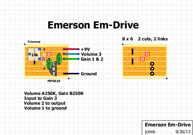
The main problem with this circuit is the biasing. The emitter is grounded, so the gain and the bias are set by the transistor itself. You will have to sort through a bunch of transistors to find one that behaves okay with this circuit. Instead you could easily add an emitter resistor and get something much more predictable.

Whether you're using the circuit as-is or as a jumping off point, I recommend finding a better-designed common emitter amplifier as a starting point. Try an LPB or a Cot-50. If you want to keep more high end try a SHO. If you want control over how much bass you include try the Naga Viper.

You'll need a mosfet for the SHO. Other than that, these circuits have a parts count that is only slightly higher than the em drive, and all of them are far better behaved.  

If you're planning on modding it, I assume you have a breadboard*. Try them all and see what you like best. Do the initial debugging before you build the vero.

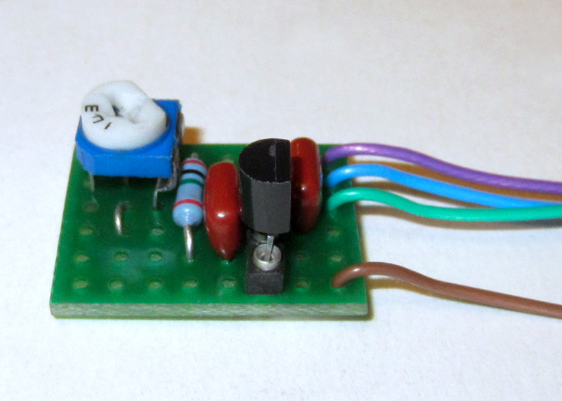
If you're absolutely married to the em drive, you'll have to post your transistor voltages (and maybe some hi-res gut shots) before we can be of much help.

* If not, buy one now.

Reply | Threaded
Open this post in threaded view
|

Re: Em drive, transistor hFe, help!

johnk
I built the non mojo version while waiting for my mojo caps to arrive. mine sounds awesome at asll drive settings. I used an MPSA18 with an hfe of 680 but I also added a 10K trimmer instead of the 4K7 resistor so I could adjust it to distort the way I wanted it to.

here's a pics of my board:


and here's my modded version of IvIark's non-mojo layout:
Reply | Threaded
Open this post in threaded view
|

Re: Em drive, transistor hFe, help!

toddvirgil
In reply to this post by induction
Induction, that's an awesome synopsis -- Thanks for taking the time to answer so thoroughly.

So, I'm not totally married to the em-drive, but honestly, this is the first circuit that I've built that is so problematic (now it seems I know why) and I wanted to work through it so I understand the way it works more thoroughly.

So, is the HFe the factor in whether or not it is biased well? or is it something more internal to the transistor (That only trial and error would solve)?

Finally another question to help me understand this circuit. The schematic of the original (which I think is how Mark Vero'd it) has the 2.2M connected to V+ like this  instead of over the collecter/base like this... what's the difference?

If the emitter is connected directly to ground, is it essentially leaking all my signal out there?

Sorry for the total noob questions... just trying to wrap my head around transistors... :)

T
Reply | Threaded
Open this post in threaded view
|

Re: Em drive, transistor hFe, help!

toddvirgil
In reply to this post by johnk
John, thanks! Looks like we were posting at the same time... Maybe I'll try out the trimmer and see if I can get something that doesn't totally suck. Thansk for the vero's! Tidy as always.
Reply | Threaded
Open this post in threaded view
|

Re: Em drive, transistor hFe, help!

toddvirgil
In reply to this post by induction
Induction, just read your link to the wikipedia article, and that made things clear as a bell. Thanks...