FACE-BENDER

classic Classic list List threaded Threaded
11 messages Options
Reply | Threaded
Open this post in threaded view
|

FACE-BENDER

jalmonsalmon


Any interest in making a layout for this one?
Be nice to have a toggle to swap out between a fuzz face and tone bender!
Reply | Threaded
Open this post in threaded view
|

Re: FACE-BENDER

rocket88
Administrator
I'll get on it tomorrow Salmon, I can't tonight I'm going to my 3rd show of the week tonight. It shouldn't talk me long.
Reply | Threaded
Open this post in threaded view
|

Re: FACE-BENDER

induction
In reply to this post by jalmonsalmon
I'd be amazed if that didn't pop like crazy in fuzz-face mode. Q1 is fully saturated, so you'll have something like 8V DC on the input (more if Q1 is silicon). I'd add another input cap with a pulldown on the fuzz face input path.

I'd also add a pulldown to the tonebender input, just to be safe.

Otherwise, it looks like a cool circuit. I'd definitely breadboard it first.
Reply | Threaded
Open this post in threaded view
|

Re: FACE-BENDER

jalmonsalmon
Yeah I am sure that circuit can be tweaked for better results.  I was thinking the same thing.
I know for the input of the fuzz face part I would add a 10n cap to ground at least or 15n
I may put that on a breadboard and mess around... I am not good at making schematics into vero though :(
Reply | Threaded
Open this post in threaded view
|

Re: FACE-BENDER

adapt
skinpimp makes this, i'm sure it is ok
Reply | Threaded
Open this post in threaded view
|

Re: FACE-BENDER

rocket88
Administrator
In reply to this post by jalmonsalmon
Salmon, I always add a pull down resistor, so no worries. When I now the layout I'll add an input cap for the fuzzface, just let me know what you want it to be. But if I'm not mistaken looking at the schematic there is a .47uf cap that's either a coupling cap when in to bender mod or input cap for the fuzzface mod.
Reply | Threaded
Open this post in threaded view
|

Re: FACE-BENDER

induction
That's true, there is a coupling/input cap for the fuzz face mode. The problem is that the input side of that cap is connected to the collector of Q1, and that collector sits at somewhere upwards of 8V DC, so the switch pop will be awful in fuzz face mode. (Not to mention it will run DC current through your pickups, if that sort of thing bugs you. Probably not harmful, just bad practice.)

What I would do is have two separate 470n caps: Keep the coupling cap as it is, but put a separate 470n between the input and the base of Q2, with a pulldown on the input side. (In other words, join the two circuits at the base of Q2, instead of at the collector of Q1.) That way you don't have to compromise on the value of the coupling cap vs the input cap because they will be completely independent.  Obviously, you can use your favorite fuzz face input cap instead of the 470n if you prefer.
Reply | Threaded
Open this post in threaded view
|

Re: FACE-BENDER

jalmonsalmon
In reply to this post by rocket88
Rocket,
Use whatever value you think is best!
I can always socket that one and play with it later to what sounds good to my ears.

thanks!
Reply | Threaded
Open this post in threaded view
|

Re: FACE-BENDER

rocket88
Administrator
Just got home, so I took a crack at it with the changes induction suggested. Take a look under the contributions section. If there's anything wrong with it let me know and I'll make the changes.
Reply | Threaded
Open this post in threaded view
|

Re: FACE-BENDER

induction
It looks like your pinout is CBE instead of BCE.

The new input cap is also not in the right place.

My description probably wasn't clear. Here's a modified schematic:
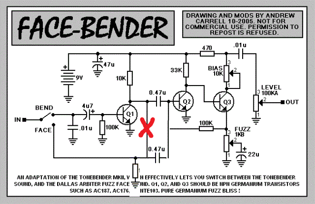


I breadboarded it last night and it popped in fuzz face mode, as I suspected it would. The pop went away when I modified it as shown above.
Reply | Threaded
Open this post in threaded view
|

Re: FACE-BENDER

rocket88
Administrator
Damn, I'll make the changes when I get home. I thought I had it as bce, cause that's how I read it when building the layout, but that's if it was PNP not NPN. That was a real silly mistake. Your altered schematic makes more sense then when I read what to do. It's probably cause I'm running on like 3-4hrs of sleep from last nights show and going to work. My mind isn't all there I guess. Lol

Are those the only mistakes?