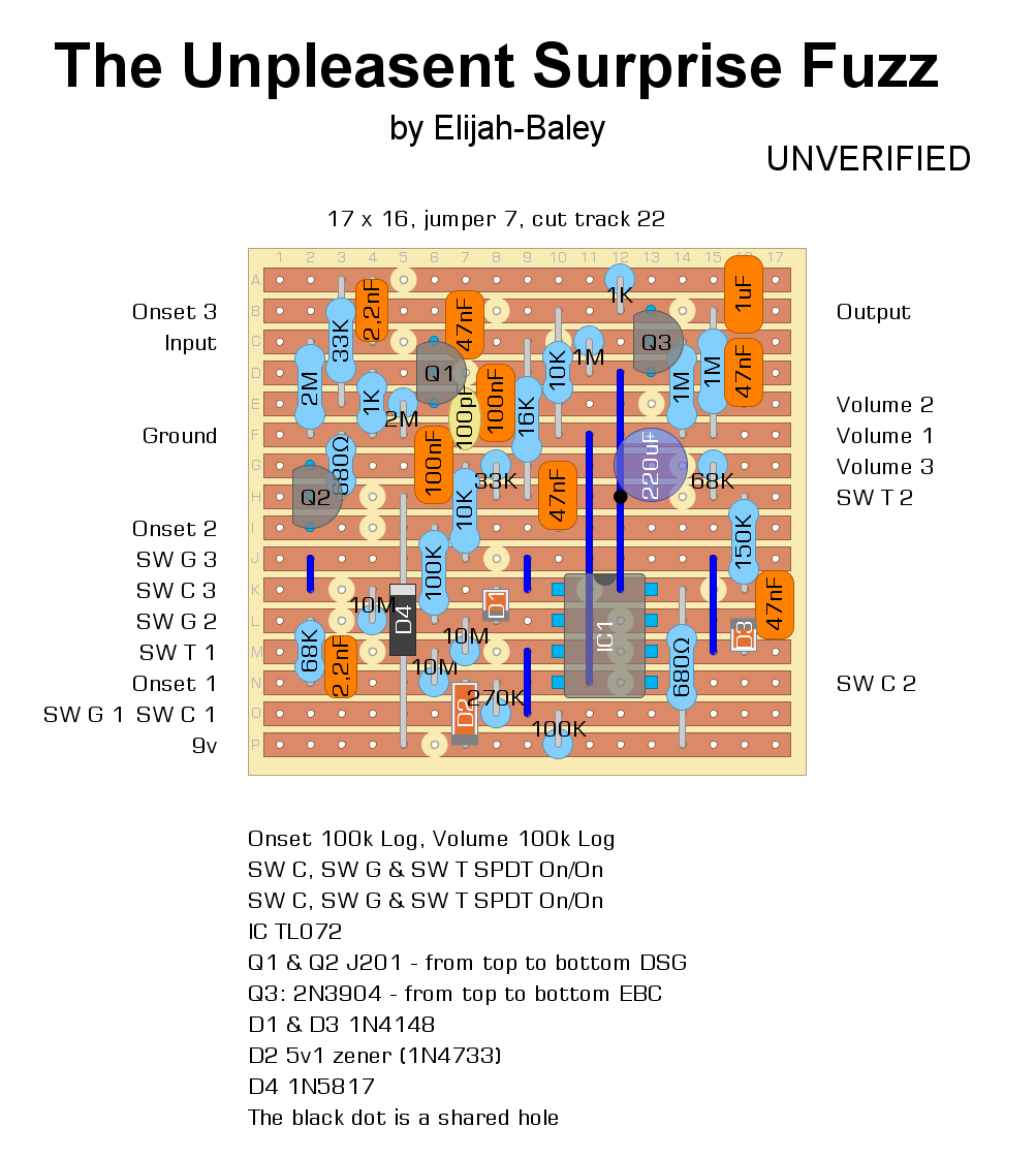
FAIRFIELD CIRCUITRY - The Unpleasant Surprise
123


123
|
I guess that's the values before fixing the pedal.
For both Q1 and Q2 you should see VCC/2. At least that's how it usually works. Best way to go would be replacing drain resisitors with 50k linear pots and bias by ear, then put back the right resistor |
|
I guess nobody saw a mistake! Sorry. My bad, of course.
 The 33k resistor in the upper lef corner goes in the Q1 source instead the Q1 gate! It's enough move the bottom side of the resistor one stripe down. This is the update layout: 
I build pedals
|
Re: FAIRFIELD CIRCUITRY - The Unpleasant Surprise
|
In reply to this post by fx-fidden
Thanks for this - I just replaced the 27k (which replaced the 33k resistor when I was aiming to grin it up to the 4v region) with a 56k which brought the Q2 drain down to approx .5v.. and.. the crush switch worked! however, the whole pedal didn't sound quite right.. like it lost its fullness .. thats the best way I can describe it..
|
Re: FAIRFIELD CIRCUITRY - The Unpleasant Surprise
|
Hello... ! Followed the updated layout and all is well!! theres there’s oscillation in the final 5-10% of the onset pot when the gain is engaged but I can live w that.. thanks for looking into it. Although, the Q2 drain with back up to my original values alternating between 2.5 and 3.5 depending on the gain switch being engaged or not.
|
|
Well.
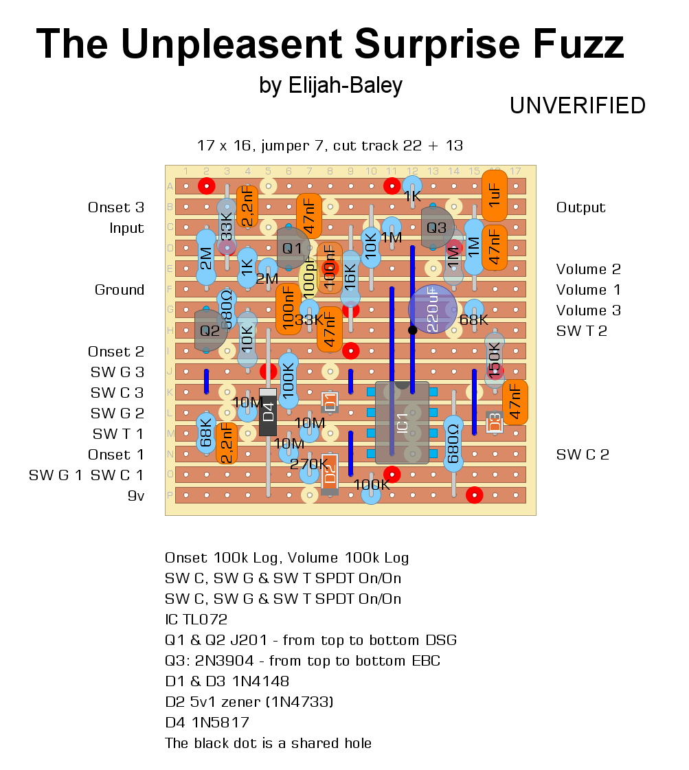
Oscillation occurs sometime in high gain circuit veroboard, it depends from the layout. Sometime input track and output track (or other spot of the circuit) are too much close, and this can rise up noises. I have an idea that nobody never had, I guess. Of course I don't know if it can be really useful, but I would like to try once to add more cut tracks in a layout to make shorter some end of tracks. It's a bit hard to explain, but I'll do an example. Do you see the 100k resistor in the last two stripes? The signal that pass in the upper side of that resistor flows to the right until the end of the board, but is totally pointless. I could add a cut track to cut the signal avoiding it passes close the signal of the stripe above. This and other cut track can help, or maybe is needless. I still don't know. I can't explain the voltages, because I don't have the board phisically, but just drank in my software. Anyway, I'll check out, again, my layout in case some other mistake is missing.
I build pedals
|
Re: FAIRFIELD CIRCUITRY - The Unpleasant Surprise
|
In reply to this post by fx-fidden
Ok, I’ve built the updated layout..
Changed the Q1 drain resistor from 16k to 36k. This gave me a Q1 drain reading of 4.3v Changed the Q2 drain resistor from 33k to 56k. This gave me a Q2 drain reading of .5v Pedal sounds great!! However.. with the gain switch off, the onset pot beyond halfway CW starts to squeal and oscillate.... I’d love to be able to fix this...!! Any ideas..?? Also, and I’m not sure about this... but it sounds like this version has more gain than the original... perhaps explains the oscillating??! |
|
a buffer at the beginning of the chain should solve the oscillation
|
|
Even in front of a fuzz? I mean, some fuzz doesn't like buffer in front. I don't know this.
Anyway, I can't find any mistake in my layout, but I modified a bit my layout doing that thing I told early. I moved some parts and I added the red cut track to make some tracks shorter. Is it crazy?  
I build pedals
|
|
Ah right it's a fuzz, yes often fuzzes don't go well with buffers, I don't know about this one (and I'm not a fuzz guy), but in general a buffer in front of the chain removes oscillations, I experienced that quite a lot of time with high gain pedals.
Your layout looks great, with in and out on each side. |
|
In and output are well separated, but maybe some tracks are too close. I don't know, because I never really experimented with this issue. I just hope that stopping to let the signal pass in some spot it can solve this issue.
Maybe tomeunknown could try to cut some tracks how I showed in my last layout (even without move parts), it's enough cut some tracks. But he said that it's ok and I don't want to pressure him. I'm sorry, but it's hard to say when I could try it. Who knows if there's somebody else who want.
I build pedals
|
Re: FAIRFIELD CIRCUITRY - The Unpleasant Surprise
|
This post was updated on .
Hey - I’ll cut some tracks tomorrow and report back.. I suspect I’ll only manage to add approx 4 or 5 given that the board is populated.
Are there any other suggestions or ways to combat the oscillation? Also, like I said earlier, it feels like there is more gain available than the original pedal which I did own.. at least from what I can remember.. even the crush/compression sounds much more intense when fully dialled CW... which is fine, although can this contribute to it oscillating? |
|
I can't be sure, but perhaps the J201 inside this Fairfield Circuitry pedal are matched, so the 16k and the 33k resistors are critical to make this pedal works as they want.
I wanted to ask you: are you using traditional transistor or smd version? The drain voltage, I think, can change the amount of the gain. Indeed, my emulation software (that I guess doesn't have matching problem with those) tells me that if I replace the 33k with a 16k I get more voltage and push the volume up. Indeed, you have over 2V in the Q2 drain. If you can try to change the 33k resistor in the Q2 drain until you get something around 0.5V and see if the pedal sounds more familiar to your ears, and tell us about the oscillation, too. I suggest you try to change the resistor before to make any further cut tracks, it could be useless mess up with the board. Thanks for your work on this layout! 
I build pedals
|
|
As I mentionned before, replace the drain resistors with potentiometers, set them to get the sound you like with the lowest oscillation, mesure the values and finally put back fixed resisors
|
Re: FAIRFIELD CIRCUITRY - The Unpleasant Surprise
|
In reply to this post by fx-fidden
Yeah I already changed the drain resistors:
Changed the Q1 drain resistor from 16k to 36k. This gave me a Q1 drain reading of 4.3v Changed the Q2 drain resistor from 33k to 56k. This gave me a Q2 drain reading of .5v Im using regular transistors. |
Re: FAIRFIELD CIRCUITRY - The Unpleasant Surprise
|
In reply to this post by alltrax74
Thanks Alltrax - this does sound eke the logical next step.. However, considering my limited knowledge (thats extending all the time with each build!) im not sure exactly how to do this.. which pot legs connect to the board? are any of the pot legs joined? how do I measure the resistance?
Also, it seems like im in the range of what ought to be correct (Q1 4.3 and Q2 .5).. would you suggest sweeping in a particular direction? "For both Q1 and Q2 you should see VCC/2. At least that's how it usually work" You mentioned this in an earlier post.. not sure exactly what you mean here. Finally, is it worth swapping the JFETs with others if have laying around..? |
|
Usually with JFets you are looking for half VCC (power supply) at the drain. This is how it works with all the amp simulation circuits here and there, but it could be different in particular circuits, and I don't know this one (were came that 0.5v from, is it a value mesured on an original unit ?)
For the pots it's very simple, remove the resistors, take 2 leads from each and connect them to the pots : one lead to the central pot lug, the other to any of the 2 other lugs. Once you have the setting you like, mesure the voltage on these 2 lugs with a DMM set to DC 20v |
|
I asked about the transistors beacuse the smd version, I think, are more accurate and easier to match.
I'd say to use potentiometers just to find the good resistance value, assuming that right the voltage are those (Q1's Vd was about 4V, Q2's Vd was 0.5V.) (Anyway, those voltage was in the replica of The Unpleasant Surprise by PedalPCB, which only provides the board.) Once found the right value resistors it should be ok, you have just to hear how it sounds and if you get oscillation. I recommend wires not so long, and input and output wires far away each other.
I build pedals
|
Re: FAIRFIELD CIRCUITRY - The Unpleasant Surprise
|
Ill give it a go tomorrow evening.. given that im already pretty close too the suggested range im not sure what ill find.. going down to 4v from 4.3v on Q1 for example isn't likely to make a significant difference? not sure if I should be going any lower than that? Also, what is likely to be contributing to the extra gain?
|
Re: FAIRFIELD CIRCUITRY - The Unpleasant Surprise
|
In reply to this post by fx-fidden
Hello...! Happy to announce a successful outcome!
Changed the Q2 drain resistor from 56k to 68k This gave me a Q2 drain reading of approx 3.8 to 4.4v. This made all the difference w regards to oscillation... whenever the voltage went above .5v the oscillation returned. It’s sounding great.. exactly as it should :) Thank you to everyone who assisted w the troubleshooting! |
|
I'm really glad of this!
 Thank you for your attempt to build my unverified layout. I'll update it soon with a nice "VERIFIED"!
I build pedals
|
«
Return to Unverified Layouts
|
1 view|%1 views
| Free forum by Nabble | Edit this page |

