First layout attempt
|
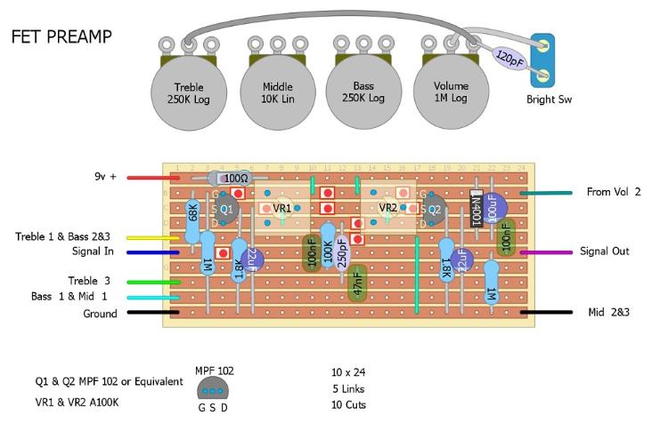
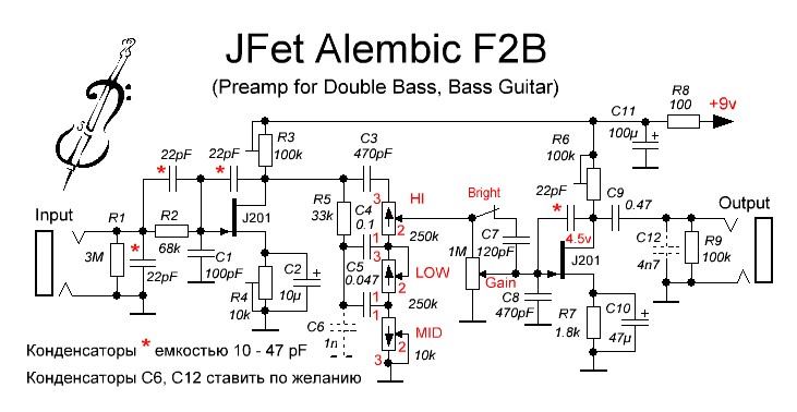
Hi,This is my first post here, I have learned a lot from this site and have built a "Timmy" and a "Zendrive" both turned out great, thanks for all the info! Recently I built a clone of a Alembic tube preamp (f-b2) single channel and although it sounded great I couldn't get rid of the hum it made, so I decided to make a Fet version and fit it into a pedal, I had two MPF 102 fets left over from a previous project and modified my build using them, sounds good and no noise. So I drew up a layout of the pedal version and would appreciate any input from you knowledgeable members, Thanks for looking, Tim

|
|
Nice one Tim.
The only real advice I can offer (and I'm certainly no expert at layouts) is to start with a specific footprint in mind. So you've 4 pots and a switch...I'm thinking 1590B or 125 box. I'd be looking for 21 wide and maybe 12 deep max! So I'd load in that size of vero on DIYLC to start with and try to squeeze the circuit into that. Just how I would try it. You could remove 1 cut and 1 link from V+ to the trimmers too and save a bit of build time. Welcome 
|
|
Administrator
|
Got to agree with Ciaran. Should work fine, but I definitely think you can easily shrink it. Building layouts takes a lot of practice to figure out little tricks to squeeze things into smaller spaces. Two pieces of advice I can give you is think about it as a puzzle, and you can make layouts smaller by sacrificing having to use more cuts and links, and/or by making the layout taller instead of going wider. Sometimes it's worth it, sometimes not.
Also, welcome man. |
|
In reply to this post by Ciaran Haslett
Thanks for your input, I will be using a 1590B enclosure the same as previous builds, the width of the board was a concern and there is a lot of empty space below trimmers, so back to the drawing board, or DIYLC in this case
 Thanks again, Tim |
|
Administrator
|
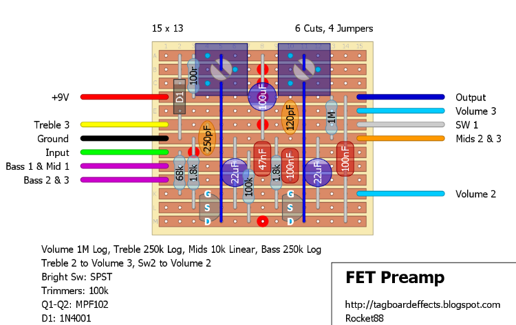
i whipped something up real quick to give you an idea of what i was talking about, and hopefully it can help you see how you can lay things out.

|
|
Administrator
|
In reply to this post by oldfartrocker
That amp in your avatar looks interesting, did you build that?
|
|
Hi Travis, Yes I did build it, It is based on a Fender Bassman 5F6A, but has a pair of 6V6s in the output section, Here is a link to my google+ where some pictures are https://goo.gl/photos/NEk691NfDQhnSbQx8 I also built all the cabinets etc. It is just a hobby for me and it is so addictive and so rewarding, I love it. Thanks, Tim Sent from Mail for Windows 10 From: [hidden email] That amp in your avatar looks interesting, did you build that?
If you reply to this email, your message will be added to the discussion below: http://guitar-fx-layouts.42897.x6.nabble.com/First-layout-attempt-tp38811p38824.html To unsubscribe from First layout attempt, click here. |
|
In reply to this post by rocket88
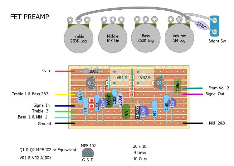
Wow, that looks great, I did a second one and got it down to 20x10, but you did even better than that this is what I did,
 Thanks for taking time to help me learn, Tim Thanks for taking time to help me learn, Tim
|
|
Administrator
|
No worries man, you're on your way. Keep at it. Like I said it all comes with practice. A lot of my first layouts were way oversized. The more you do it the better they become. You've got to visualize components and try to think what's the best place for them so you can get things neat and little cramming.
Like I said look at it as a puzzle. You may have to change things around as you go, and change you're initial plan for components. When I did this layout I thought to myself I want the trimmers out of the way, cause they take up a huge amount of space, so either too or bottom of the layout. Then I thought I want the input away from the power, and need the components from the FETs to layout flat to ground, which told me that I need to be at least 4 rows. Then everything else sorta fell into place in between. |
|
Welcome and nice layout! There definitely is an "art" to drawing the vero layouts. I try make mine compact, but keeping mind not to put large components (like big electrolytics) too close together. I'd rather add a few columns if it means the build will be easier and I can fit it into the enclosure of my choice.
One quick note - you probably don't need 100K trimmers for your MPP102 JFETs with 1.8K source resistors. 20K will do (and probably even 10K). Keeping these trimmers to roughly twice the expected drain resistance makes it easier to dial in your desired drain bias. |
|
Thanks for the welcome and advice, I intend to socket the MPF102s so I can try others like the J201, so will 20K trimmers be OK for other JFETS?
Thanks again, Tim |
|
20K will work for 2N5457, J202, MPF102 and JFETS with similar Vp and Idss. J201s will probably need 50K (drain resistance will be about 20K for a source resistor = 1.8K and drain voltage of 5V). If you want to try a range of JFETs, use 50K.
|
|
Administrator
|
In reply to this post by oldfartrocker
Very cool! I built a 5e3 and I absolutely love it. I need to build the 5F6A, you're right it really is addictive
Unfortunately I can't seem to get that link to work. I do custom cabinets for work, so I picked up on that rad cabinet work right away. It's not really the aesthetic that I would do personally, but the craftsmanship looks very beautiful and impressive from what I can see. I'd love to see more |
| Free forum by Nabble | Edit this page |


