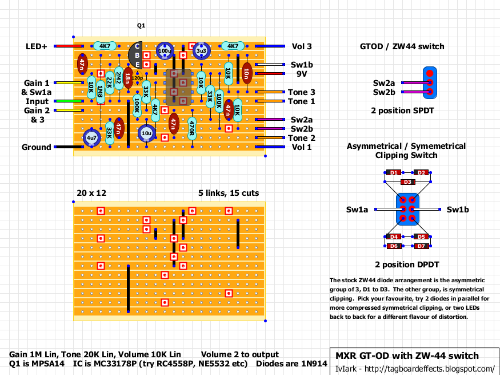
First vero build: MXR GT-OD, little question
|
I know, I know, probably it's not the easiest way to start with veroboard, but... I was so excited to get my hands on my solder iron that I started from the hardest one I chose from the various layout, the other one beeing "BlackCat OD1", "Maxon 808" and "Menatone Red 3 Knobs".
Hope everything will be fine!!!  Anyway, I already noticed a difference from the other layouts: this one got a "LED+" wiring (top left corner) that I do not find in the other I mentioned...  I'll be (obviously) using Mark's "Offboard Wiring", I'm just wondering do I simply need to omit the red wire from the DC jack to the LED, and use instead the red wire coming from the board? Will I also have to omit the LED resistor? Sorry for the newby question...and thanks in advance for any help you'll share with me! Thanks a lot! |
|
Administrator
|
The offboard wiring layout I did is just a general layout that you could use for any random build, and I show the LED and current limiting resistor along with the connections just to make it obvious how it all hooks up. In a lot of my layouts (where I have space without having to add additional columns) I will add the current limiting resistor to the board so you don't have to mess around trying to solder a resistor in series with wires from the board. So when you see LED+ on any layout, that connects directly to the LED anode without having to add an additional resistor, then the cathode goes to the switch which is then grounded when the effect is turned on, which completes the LED circuit and illuminates.
|
|
Hi Mark,
thanks for the reply, I thought it was something like this, but I need some reassurance, beeing a completely newbie! If everything goes well I'll post some pics of the build! Thanks again! |
|
What I always do is that I take a 2.7k-3.3k resistor right from the DC jack and wire it to the LED+ and then the LED- to the 3PDT switch. I usually keep the LED very close to the switch so it makes for a compact wiring and takes virtually no space, allowing me to keep the jacks close to the switch, for more circuit space in the enclosure!
www.pedalprojects.com
www.facebook.com/pedalprojects |
Re: First vero build: MXR GT-OD, little question
|
In reply to this post by Kost1978
hey man, just a head's up on being in your position. My first build was the Black Cat due to parts count, and as it turns out it isn't the # of parts that got me, but my inability to deal with a bad soldering iron in tight soldering situations.
When you populate your board, you're going to figure out really quick that it's a tiny, tiny little area. I did the Black Cat layout the first time as-is on the layout guide, and I ended up with a lot of solder bridges, to the point where I'm just starting over again after I get a better soldering iron. I'm going to alter the next build a bit by stretching some of the layout horizontally along the strips to give myself a little elbow room. My single solders were great, but when there were close neighbors, things started getting messy with the amount of time I had to leave the iron in place to get anything done. It's like the heat went everywhere but the place I wanted it to go. USE SOCKETS. If I choose to toss this board, I have like what, $0.50 of components on it. If I placed the IC, I would have been pretty irked. |
|
I know, I know, nobody here slept because of the lack of updates in this thread eh??
 Wanna know how it went with my first build? Well, it went bad!!! At the end of the board population (yes exactly at the end...) I realized I cut the stripboard the wrong way: columns at row's place and viceversa... So, i unsoldered everything (luckily I too use sockets), cut a new 20x12 and started over again. But the pedal is not working as expected, well, it's not working at all, no sound is coming from the effect beside the bypass mode... It's not the switch cause I tested it and even connected the citcuit directly to the jacks, so it's probably something wrong on the board, and right now I do not want to troubleshoot the components (also tried to switch the IC), I'll probably rebuild it again in the "next future" from scratch. Anyway, after the failure I started and completed the "Black Cat OD", this little beast is working fine (still have to test it at proper volume, but...it'sworking!), so I could prove to myself to be able at least to complete a small project! To reply to Jon, I noticed the difficulties in soldering this tiny little spots, but didn't have so much problems, I didn't create any bridges (as far as I can tell) and the Black Cat seems to work as expected. Don't wanna say I'm great with the solder iron, but at least it didn't seem much different to me than soldering a effect kit's PCB. Anyway, I'll probably find out how good I am with my next one, still have to decide between Menatone Red Snapper 3 knobs or Maxon 808. So, end of the first chapter in my stripboard experience, I have to say that, even if I swore a lot and my girl did not talk to me for 12 hours, it was really, really fun! Thanks again Mark and everybody to contribute to this site!  |
«
Return to Open Chat
|
1 view|%1 views
| Free forum by Nabble | Edit this page |

