Frantone Creampuff - general build/debugging questions (no sound)

classic Classic list List threaded Threaded
20 messages Options
Reply | Threaded
Open this post in threaded view
|

Frantone Creampuff - general build/debugging questions (no sound)

tracer03
This post was updated on .
I tried putting this one together over the weekend, did a test wire up outside of the box, and got no effect. No sound, anything. So - for debugging I followed these steps in order:

1. Went over all of my solder joints and track cuts with a magnifying glass, reflowed any joints that looked suspect.

2. Checked it with my multimeter for continuity, and didn't get any unexpected shorts/bridges.

3. Checked parts placement against the layout, made sure everything was oriented and positioned correctly.

4. Used an audio probe to poke around the circuit. I got unaffected guitar signal in some areas, but anywhere after the IC, I got no sound.

What I *did* notice was that - when connected to a fresh 9v battery, none of the LEDs light up, which implies that there is a bad connection somewhere (I expect that the LEDs on the L side of the board should light up, per the build comments here on the site).

I'm familiar with the 'basic' fault finding and debugging, but there are a couple of questions I have that I'm not clear on:

1. IC Orientation. It's hard to tell from the layout, but it looks like Pin 1 of the IC should be oriented towards the upper L of the diagram. My ICs really don't have an indicator as to which pin is '1', but looking at it, holding the chip horizontally so the text reads normally - Pin 1 would be the left-most PIN on the bottom row, correct? And is this the correct placement for this circuit?

2. Measuring IC voltage. This is as simple as using the multimeter, connecting black to ground and probing each pin with the Red probe, measuring DC voltage at each step, correct?

3. Is there a 'simple' way to hook up and test for output, or do ALL the control pots NEED to be attached for the circuit to properly function? I've been using alligator clips for the in/out jacks and the pots, but is there an easier way?

Thanks in advance.

mug
Reply | Threaded
Open this post in threaded view
|

Re: Frantone Creampuff - general build/debugging questions

mug
Hey tracer,

I'm not familiar with this specific pedal, but from the layout I'm sure the pots need to be there - volume 2 carries the signal to your output for example.

Measuring of voltages works exactly as you described!

No clue about the IC orientation - all ICs I've seen had an indicator (small cut or dot at one end).

For easy testing a test box is a nice gimmik: here

Maybe pictures could help the pro guys here to help you further!
Good luck with your build!
Reply | Threaded
Open this post in threaded view
|

Re: Frantone Creampuff - general build/debugging questions

tracer03
mug wrote
Hey tracer,

I'm not familiar with this specific pedal, but from the layout I'm sure the pots need to be there - volume 2 carries the signal to your output for example.

Measuring of voltages works exactly as you described!
Sorry, should have been clearer: I know that in most of the circuits the volume/tone/gain are pretty essential, I was just wondering if there were any 'tricks' or shortcuts to making sure that the circuit had effected output without having to wire everything up.

As for a test box - I was using this - http://pcb.delyk.com/utility-boards/40-effects-tester-mk-ii-kit.html - but it didn't seem to be working when I tested it with my first build, the Lovepedal Silicon Fuzzmaster. I may have to revisit that test circuit - could be a bad build. Otherwise, looks like I'll be building that test box tonight.

Cream Puff Pics to come soon.
Reply | Threaded
Open this post in threaded view
|

Re: Frantone Creampuff - general build/debugging questions

Beaker
Wiring the pots to the circuit is pretty much essential. You can cheat to some extent and wire in resistors to simulate the pot but this is almost as much work as wiring up the pots themselves.

IC's have a round dot over pin1 or a semi-circular notch at the top (pin 1 and 8 if it's a 8 leg chip),
or sometimes they have both.

Pins are numbered as follows:

1o    8
2      7
3      6
4      5

(The o after the 1 indicates the orientation dot.)

Like this:


Take another look at the drawing - you can see the semi-circular notch at the top of the IC - it's faint, but you can see it.

Almost all layouts have the notch at the top, but make sure you check that it is!
Some layouts, especially ones with more than one IC may have one or more ICs "upside down".

Reply | Threaded
Open this post in threaded view
|

Re: Frantone Creampuff - general build/debugging questions

Travis
Administrator
When I check a board before boxing and final wiring I solder the wires to the board and leave them longer than I need. I plug the free end of the wire into my breadboard where it connects to a trimmer or board mounted pot
Reply | Threaded
Open this post in threaded view
|

Re: Frantone Creampuff - general build/debugging questions

tracer03
In reply to this post by Beaker
Okay, checked the IC orientation, that's correct.
Did another continuity check with my meter, no issues found.

I'm having trouble getting photos from my phone to the computer to post shots of the board and layout, so that's still forthcoming. If I can't get the photos posted, I may just cut another piece of stripboard and start again.

I *did* see something, HOWEVER, that made me curious...on further inspection of the component side of the board, I may have spotted an issue. The 1 uF/10 uF Radials and 100 pF ceramic to the upper left of the IC position are crammed in there pretty tight, and may not be making a good connection.

Because I have larger radials, to accommodate the larger components, could I just 'add' another column or two between columns 7 & 8 (counting from the left)?

Reply | Threaded
Open this post in threaded view
|

Re: Frantone Creampuff - general build/debugging questions

Beaker
Yes you could, it won't do any harm. Or you could just snip out the 100pF and put it on column 1 (to the left of the 1.5k resistor).

This layout does work - I've built a couple and it's one of my favourite pedals.
Reply | Threaded
Open this post in threaded view
|

Re: Frantone Creampuff - general build/debugging questions

tracer03
In reply to this post by Travis
Travis wrote
When I check a board before boxing and final wiring I solder the wires to the board and leave them longer than I need. I plug the free end of the wire into my breadboard where it connects to a trimmer or board mounted pot
*slaps forehead* D'oh! That's brilliantly simple!

Beaker wrote
This layout does work - I've built a couple and it's one of my favourite pedals.
I know other people have had success with the build, so I'm sure it's either a component/board problem or Operator Error (likely the latter...)

I'm going to try and connect everything via breadboard and see if I can locate the fault. Since my phone still isn't cooperating (I think I need to cave and update the IOS), I'll tinker with it and see what I can find...
Reply | Threaded
Open this post in threaded view
|

Re: Frantone Creampuff - general build/debugging questions

tracer03
Okay, didn't get to breadboarding, but I went over my solder joints, cut the traces, verified the IC was inserted correctly and hooked up the audio probe. Still no sound. BUT...I noticed that both the IC AND The battery started getting warm fast. Unhooked everything, let it cool down ,and swapped the IC for a fresh (new) one - hooked it back up, and...same deal. Battery and IC heat up pretty quick. Which tells me there's a short somewhere. I'm going to breadboard this one and get it working, then I will cut a new board and try again.

In the meantime, this is the type of socket I am using - any issues with this?


Reply | Threaded
Open this post in threaded view
|

Re: Frantone Creampuff - general build/debugging questions

Beaker
It may indicate a short, but it could equally indicate a component, link or cut positioning error.

Check your cuts:

Are all of them there? Watch out for hidden cuts.

Are they really cut? Use a multimeter to check for continuity across your cuts.

Are they in the right place?

Have you made the common rookie error of turning your board copper side up, then making the cuts as shown on the layout?

Then check your links, then your components, then your off-board wiring.

Those chip sockets are fine by the way, in fact they are the best ones to use.
Reply | Threaded
Open this post in threaded view
|

Re: Frantone Creampuff - general build/debugging questions

tracer03
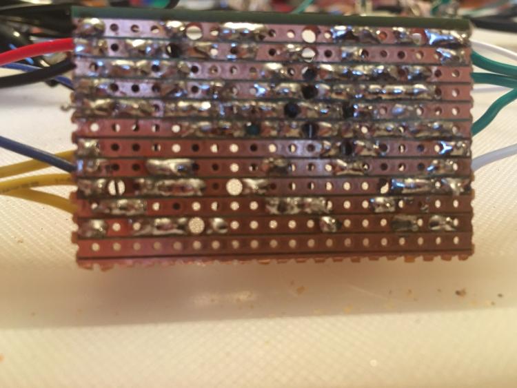
Okay, I re-cut the board last night, and rebuilt it. I made sure that all the cuts were properly placed (and in the right position based on the board image, etc.).

Before soldering components, I checked continuity across the board - no issues there. I also checked each component to make sure it was correct (resistors resisting at the proper ohmage, leds working, caps rated at the correct value. The only thing I didn't know how to test was the IC or the diode).

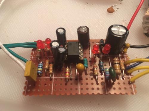
Soldered all the components, then took an X-acto and ran it between all the strips to clear any possible bridges.

Wired it up with pots and jacks, then hooked up a battery and alligator clipped some jacks. No Sound.


So, broke out the logic probe, and started following the circuit. Cleanness in, no issues up to the IC, and then dirt out on pin six. I get dirt up to the 330pf ceramic cap. I get signal at the fifth row from the top of the board, but testing at the fourth row (the other side of the cap), no signal. I replaced the cap, and the same thing happens.

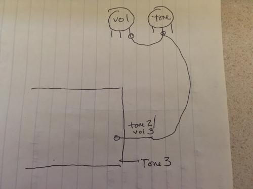
I'm not quite sure how to follow the schematic against the layout, but it looks like the 390pf in the schem here is what it's supposed to be - and i'm not sure where the circuit takes the signal.

Schem I am using (don't know if it's correct, but it's the only one I could find) -- > Baja Man Pream Cuff Schematic

Also swapped the IC, just to see - same thing.

So - not sure what to do next...halp?
Reply | Threaded
Open this post in threaded view
|

Re: Frantone Creampuff - general build/debugging questions

tracer03
Pics!

Yes, there's an extra row at the bottom. just didn't feel like trying to make a thin cut with my big fat sausage fingers.

Cream Puff Board Top

And the Back (apologies for the focus, seems that's the best I could get...)


Will try to get a clearer one of the back and post it to Photobucket.
Reply | Threaded
Open this post in threaded view
|

Re: Frantone Creampuff - general build/debugging questions

tracer03
Links to bigger pix:

Board Back 1

Board Back 2
Reply | Threaded
Open this post in threaded view
|

Re: Frantone Creampuff - general build/debugging questions

tracer03
Also: the layout says that "Tone 2 and Volume 3 connect together, there's a dummy connection for those on the board" - so I wired it as shown here in my highly detailed diagram.


Is this the correct way to wire this, or is there a better way? Just want to explore every possibility here, since the circuit seems to be making fuzz, just not outputting anything...
Reply | Threaded
Open this post in threaded view
|

Re: Frantone Creampuff - general build/debugging questions

tracer03
More info - voltages:
Reading off a fresh 9V.
1 - 4.17
2 - 4.32
3 - 4.32
4 - 0
5 - 4.43
6 - 4.35
7 - 4.21
8 - 8.68
Reply | Threaded
Open this post in threaded view
|

Re: Frantone Creampuff - general build/debugging questions

Marbles
It's hard to see, but it looks like the most left bottom 10uf cap is 1 row too high.

Hard to see in an angled picture though.

Also: The tone3-vol3 in your drawing is correct. But only if the pot is facing up. If not, you have 1 and 3 mixed up.
Reply | Threaded
Open this post in threaded view
|

Re: Frantone Creampuff - general build/debugging questions

tracer03
Marbles wrote
It's hard to see, but it looks like the most left bottom 10uf cap is 1 row too high.

Also: The tone3-vol3 in your drawing is correct. But only if the pot is facing up. If not, you have 1 and 3 mixed up.
Oh. My. God. I can't believe I missed that with the amount of times I compared the board to the layout. You were correct - I moved the 10uF cap down to the proper position, and I have glorious Creampuff Fuzztone!

Thanks a million!!
Reply | Threaded
Open this post in threaded view
|

Re: Frantone Creampuff - general build/debugging questions

Marbles
No Problem, glad it's working!

I have the same. I can look over it 100 times. 2 pairs of eyes see more than 2 :)
Reply | Threaded
Open this post in threaded view
|

Re: Frantone Creampuff - general build/debugging questions

Beaker
Glad you got it sorted - good spot Marbles - I failed to notice that one too.

I call it "solder blindness" - the inability to spot an obvious mistake, made worse by multiple attempts to find it! The more you look at it, the less likely you are to spot it. It happens to many of us here so don't feel bad.

If I have a board that is wrong and I can't spot the error quickly, I have learned to walk away and leave it for a few days. In that time my brain resets and I can usually spot the error very quickly when I come back to it.

Reply | Threaded
Open this post in threaded view
|

Re: Frantone Creampuff - general build/debugging questions

Marbles
Words to live by! :)I'm glad I took that advice from you guys: Walking away and looking at it fresh has saved me a lot of frustration (and screaming and crying: I will never be able to do this!!!)