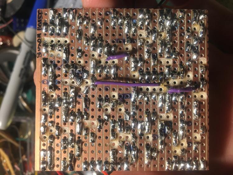
Friedman buxom boost

Friedman buxom boost

|

Re: Friedman buxom boost
|
|
Re: Friedman buxom boost
|
|
Re: Friedman buxom boost
|
|
Re: Friedman buxom boost
|
|
Re: Friedman buxom boost
|
|
Re: Friedman buxom boost
|
|
Re: Friedman buxom boost
|
|
Re: Friedman buxom boost
|
|

Re: Friedman buxom boost
|
|
| Free forum by Nabble | Edit this page |