Fulltone Secret Freq

classic Classic list List threaded Threaded
8 messages Options
Reply | Threaded
Open this post in threaded view
|

Fulltone Secret Freq

kenfoe
Hi,

I traced down the Fulltone Secret Freq, which was kinda tedious since it's a multilayer pcb with all signal traces in the middle plane - top and bottom plane is ground. Also, the gyrator is covered in gray goo and I had to simulate the values to get the right frequency response.
Since creating vero layouts is not my cup of tea (I'm more a smd-layouter) - can you do this? I think it's pretty easy, since it has no input/output buffers, and only one double-opamp + one gyrator: http://freestompboxes.org/viewtopic.php?f=7&t=17993&start=20#p259935

Thanks =)
kenfoe
Reply | Threaded
Open this post in threaded view
|

Re: Fulltone Secret Freq

Zanius
Hey kenfoe!

I started doing this, but when I got to the end I found something odd. Now I'm not so experienced myself and maybe it's a thing. On the output side of the circuit, just before the "highs" section, there are two resistors (R13, R14) in series. That doesn't seem right to me. Maybe one of them is before and one after the "highs" section? Or maybe they owned too many 10K resistors and didn't want to buy some 20K? lol

Check it out again and let me know.
Reply | Threaded
Open this post in threaded view
|

Re: Fulltone Secret Freq

Zanius
Since I made it, I might as well post it.


I'll leave it as it is for now until we get some clarification on those resistors. I'll update after that
Reply | Threaded
Open this post in threaded view
|

Re: Fulltone Secret Freq

kenfoe
Hey Zanius!

Wow, that was fast - thanks for your effort! And good catch! Indeed, thats uncommon, but for this particular pedal, it's the way it was. It seems like Mr. Fulltone used his pcb for a second version of the secret freq, so he soldered other components into the onto the pcb than it was planned originally: in the place where the frequency pot had to be soldered, there was only a resistor (see attachment). Also, the gyrator is an additional circuit seemingly he added later - or at least I think so, since it's not incorporated into his main pcb and he had to run individual wires from the main pcb to the gyrator.
You can replace R13 and R14 with one single resistor of 20k without problem.
note that there is a resistor in place of the freq pot
Reply | Threaded
Open this post in threaded view
|

Re: Fulltone Secret Freq

kenfoe
Just to make sure, I was talking about this resistor - this is one of the 10k resistors...
Reply | Threaded
Open this post in threaded view
|

Re: Fulltone Secret Freq

Zanius
This post was updated on .
Ok then! I doublechecked everything, I think it's correct

***Updated****


Let us know if you try it!

*Edit* Also try to find out the kind of pots used, Log or Lin. It should be marked on the pots.
Reply | Threaded
Open this post in threaded view
|

Re: Fulltone Secret Freq

kenfoe
Hi Zanius,

thanks again! Very nice looking layout.
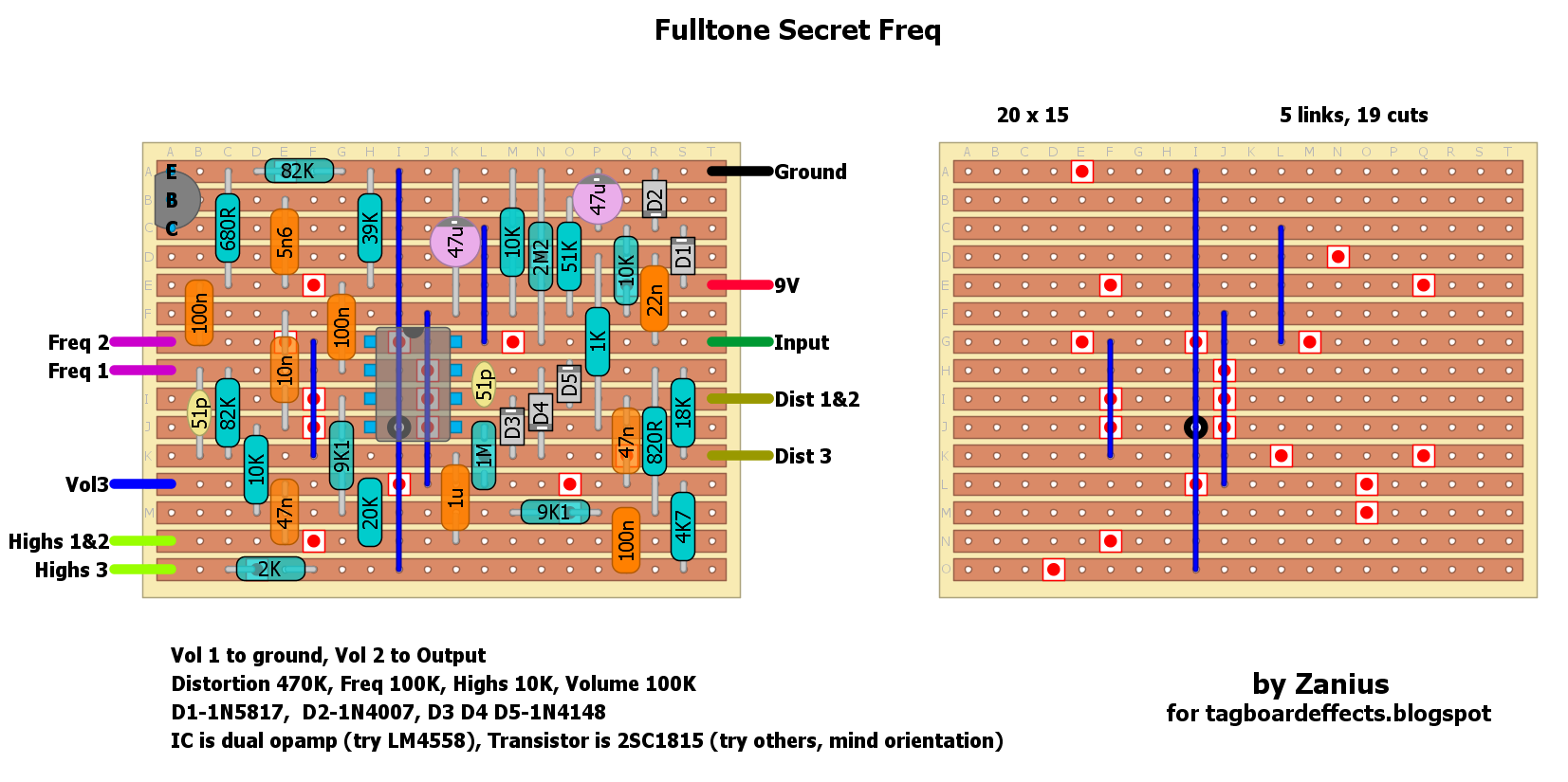
I updated my schematic, because I forgot to mention something: The OP-amps part marking has been sanded off in the original secret freq, therefore I couldn't find out the part number. In the schematic v1.0 I labeled it as AD822, which is my ECAD-softwares standard op-amp. I suggest to change it to the 4558 (pinout is identical).

And for the transistor: this is a wild guess too, since it's covered under gray stuff. But I think the 2SC1815 is quite common and a nice low-noise type, so that's ok.

Please finde the new schematic here: http://freestompboxes.org/viewtopic.php?f=7&t=17993&p=259951#p259951

Would be nice if you could change the components =) And sorry I forgot to mention it earlier...

Reply | Threaded
Open this post in threaded view
|

Re: Fulltone Secret Freq

Zanius
Ok, updated! Since you have the original you can try and see what sounds more similar.
Thanx for your effort on tracing it!