Guitar > Modular (?s about gain factors and env followers)
|
Hey all
(sorry about creating two topics in a single day.. the people on this forum are knowledgable and kind, I wanted to post here over MuffWiggler/ElectroMusic/etc despite there being more modular users over there) I have my DIY-eye on a few modular units I'd like to use with my guitar. While the guitar stompbox world is growing at an incredible rate and useful innovations are constantly being made, the eurorack/modular world is growing even faster IMO. There are so many companies releasing modular units that are capable of doing things that guitar stompboxes are just now being able to come close to... some things that stompboxes still can't touch at all. I've been doing a lot of reading about modular and how to integrate high-impedance signals into a eurorack setup, and I'm coming across a few issues. I was hoping a few people here could help me answer a few questions I have: 1) Most eurorack modular pieces are designed to take in line-level, low-impedance signals. As far as I understand, guitar signals are high-impedance, and that requires a conversion. When it comes to impedance and gain, some units like the Doepher A119 have a high-Z input with a "gain" knob with a gain factor of 0 to 500. Will driving up the gain of a signal cause the impedance to drop? Are there any circuits on this site that will bring down the impedance of my guitar signal, and also bring up the gain to line-level signal ranges?.. ideally something like a gain factor of 500 accessible? 2) Most units require a +/- 15V power supply. I'm pretty sure I know the answer to this, but is a guitar stompbox's +/- 15V power supply (like the layout of this namesake on this website) the same as a eurorack +/- 15V power supply? A power supply is a power supply is a power supply, right? For some reason I have this fear that I will feed it "the wrong" 15V and fry the thing. 3) Regarding a guitar pickup: a guitar pickup outputs a varying voltage based on the vibration of the strings caught by the magnets in the pickups, right? In a sense it creates a waveform that is then driven down the cable and into the amp..? Is the function then of an envelope follower to smoothen out the waveform created by the pickups, so to make the signal easier for whatever circuit is down the line to process the signal? What is the difference between a signal and an envelope follower's output of a signal, taking a guitar as an example? Sorry for the barrage and rambling, and thank you for taking the time to read. If you guys haven't dipped your toes into the modular world, definitely check it out. Some of these machines can create pretty amazing sounds. Thanks guys Alex |
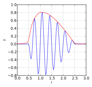
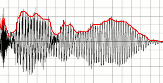
Impedance and gain are mostly independent, so increasing gain does not necessarily decrease impedance. To increase voltage you want a clean booster. To decrease impedance (almost to zero, if necessary) you can use a buffer. The buffer should go after the booster. If the booster has a low output impedance (AMZ mosfet boost, MXR Microamp, etc.), then you can skip the buffer. A gain factor of 500 is pretty unrealistic with pedals, and probably unnecessary unless the original signal is extremely small. Take a 100 mV amplitude signal (roughly pickup output level), 0.1 * 500 = 50V. So you'd need a hefty power supply and robust components. But according to Wikipedia, line level for consumer equipment is referenced around ~0.4 V, and for professional equipment it's ~1.2 V. These voltages are easily achievable with a Microamp or something similar. Other than AC vs. DC, volts is volts, for the most part. Make sure your psu can supply as much current as you need and you should be fine. A guitar signal, seen from close up, looks like a bunch of closely-spaced squiggles. Seen from further away, those squiggles combine to form a larger shape or outline, called the envelope. An envelope detector translates the approximate amplitude of the individual squiggles into a voltage that can be used to control some parameter of the circuit. Here are a couple of examples from the Wikipedia article on envelope followers (the black or blue curves are the signal, the red curve is the envelope):   |
|
Induction, thank you for the reply. super helpful.
Just to clarify a few things.. 1) so if I were to send my guitar thru an AMZ Mos Boost or MicroAmp that would provide me both the low impedance and the signal strength I would need to bring my signal into line-level synth-out territory? and Re: the envelope follower, the output of the envelope follower is the red line in that first graph, correct? It's essentially a grainy-er picture of the guitar signal, which makes the signal easier for the equipment to process?.. as opposed to all that detail in the original complex guitar waveform? Is there a general classification scheme that separates equipment that prefers the envelope follower output as opposed to equipment that can just as easily handle/prefers the guitar waveform? I've seen envelope followers in auto-wah type circuits.. which part of the auto-wah circuit forces the designer to run the guitar thru an envelope follower before hitting the filter part of the circuit? I'm guessing some part of that filter can't easily handle complex waveforms.. right? Or is it all about thresholds, and since the envelope follower signal is smooth and continuous it more steadily and predictably dips above and below the threshold, as opposed to a guitar's signal that would jet up and down across the threshold so fast and frequently that it would just overload things? |
Re: Guitar > Modular (?s about gain factors and env followers)
|
It's not necessarily about complex waveforms or overloading, but rather about the function of the circuit. The thing to keep in mind is that a guitar's unadulterated output signal is AC while the output from an envelope follower is DC. You'll notice if you do some more digging that an envelope follower is a form of rectifier, and actually a commonly-used circuit block for this application is something called a <a href="http://">precision rectifier . An auto-wah uses some variety of voltage-controlled filter to make the wah sound, and this can't operate off the AC from the guitar. For example, in the Mutron circuit, the VCF is LDR-based and the envelope follower supplies variable DC to an LED that interacts with the LDR in the VCF. In other circuits it might be a transistor-controlled element and the DC from the envelope follower becomes a variable base voltage for the transistor. If you're interested in auto-wahs, I would have a read of this article; it explains very well and I'm actually studying it myself for some auto-wah designs.
Through all the worry and pain we move on
|
|
In reply to this post by notnews
Yes. Yes. It's not exactly a simplified picture of the guitar signal, it's a picture of the amplitude of the guitar signal, with frequency information removed. It's not that it's easier for the equipment to process, it's just that it's often useful to control some parameter according to the volume of the guitar signal. The signal envelope is a different beast than the signal itself. You wouldn't want to listen to the envelope, you generally just use it as a control mechanism. So it's not that some equipment can't handle the signal, it's just that the envelope is more useful for what the designer is trying to accomplish. For example, in a normal wah pedal, the resonant frequency of the filter is controlled by a pot. You move the treadle up and down to move the resonant frequency via the pot setting. In a basic autowah, on the other hand, the resonant frequency is controlled by the volume of the input signal via an envelope follower. The louder the signal, the higher the frequency of the resonant peak. Likewise, you could make a compressor by adjusting the gain of a circuit according to the envelope: the higher the envelope voltage, the lower the gain. The Orange Squeezer can be thought of that way, except instead of reducing gain, high envelope voltages decrease the resistance of a jfet as it dumps the input signal to ground. |
«
Return to Open Chat
|
1 view|%1 views
| Free forum by Nabble | Edit this page |

