HELP cant get NPN germ emulation to work??

HELP cant get NPN germ emulation to work??

|
I dont think i understand the matching transistors for this.#1 Do i just match the for hfe? #2 Do i need all 4 transistors to match exactly the same or can it be Q1 and Q2 matched then Q3 and Q4 matched but different from Q1 and Q2? I'm sooo confused LOL
|
|
|
Include a link or something, so we know what you're talking about.
Assuming it's this, the transistors don't have to match at all. Q1 and Q2 should be the same type (eg 2n3904), and Q3 and Q4 should be the same type. The trimmers are used to dial in the combined hfe of each piggyback pair. Here's what I recommend: Set up a transistor tester on a breadboard or a dedicated vero with sockets for the transistors. Pick two transistors of the same type at random, plug them in, and use the trimmer to dial in the hfe you want. Mark the two transistors and note the final resistance on the trimmer and the gain. Do it again for another pair of transistors. Set the trimmers to the resistance you chose before soldering them into the vero, or just use fixed resistors. You'll need to have some idea of the hfe's you want for each stage in advance (plenty of advice on the internet for that), or else you'll need to breadboard the whole circuit so you can try more than two pairs and see what you like best. Or you can just build it and twiddle the trimmers until you like it. I recommend the breadboard. Lots more info here and here. |
Re: HELP cant get NPN germ emulation to work??
|
|
Why would I need to include a link? There is only 1 germanium emulation circuit on this site.i assumed whoever wanted to help would already know that.
|
|
|
Including a link makes it easier for us to help you for several reasons.
- We discuss lots of circuits here, not just the ones that have layouts on this site. - Not everyone has an encyclopedic knowledge of which layouts are on this site. - Making someone go searching for the circuit you're talking about, makes it much less likely that they will invest the time to help you. For example, I made a guess about what you were asking about based on the fact that I've built that circuit, but I didn't use the layout from this site. I read about the idea on the links I gave you and then made my own layout. Whether IvIark has posted a layout for this circuit or not wouldn't stop me from helping you if I am able, but the phrase I associate with the idea behind this variation of the circuit is 'piggyback transistors' not 'NPN germ emulation'. I made a guess and then searched this site. I could just as easily have decided that I didn't know what you were talking about and ignored your question. You certainly don't have to include a link if you don't want to, you just reduce your chances of getting the help you're asking for if you don't. It's up to you. |
Re: HELP cant get NPN germ emulation to work??
|
|
I'm not sure i understood what this forum is for then.I thought this forum was just for tagboard effects.so when i posted a question,it comes up on other sites as well as this one?I am sorry for not posting a link then.I am new to all this blogging stuff.i dont use all these facebooks and twiiter stuff.I basically need to figure out what IVIark ment by matching the transistors.I matched each of the 4 transistors and found hfe of 376 then put them into the sockets in my circuit from tagboard.If all 4 transistors are the exact same hfe shouldnt this circuit work? I only get a very short cut off splatt noise with my bias fully ccw and trims Q1&2 full cw and Q3&4 ccw.When i turn any of the trims or bias in opposite direction the signal mutes completely.
|
|
|
When you post here, it only shows up here, not on any other sites. But discussion on this forum is not limited to layouts that are posted on the main site. You can ask for help with builds you make from a layout of IvIark's or mirosol's, or you can ask for help with other builds/mods/commercial units. Or you can just have general circuit-related discussions that are not related to a specific layout or debugging problem. There's no rule that you have to post a link, I just suggested it because I thought you'd get more responses that way.
From reading IvIark's text on the layout, I don't think he mentions transistor matching at all. Maybe the confusion comes from this statement: "1. Take two identical random silicon transistors (for more mojo: your fav fuzz silicons)" 'Identical' just means they should be the same part number (2N5089, 2N3904, etc.). But 'random' means they don't have to be matched for hfe or anything else. The way you describe the behavior of your circuit, it sounds like it isn't biasing correctly. This one might be difficult to twiddle into operation with the trims. Let's start with some basic questions: 1. What kind of transistors are you using, and how did you measure the hfe? 2. Do you have a breadboard and a DMM? |
Re: HELP cant get NPN germ emulation to work??
|
|
I already have the circuit built,but yes I do have a breadboard and DMM.I chose to use 2N 3904 transistors to start with.I built IvIark Vero version and used regular trims instead of inline trims.I attached these trims with about 3 inches of wire on each contact.I know it's not bias correctly for sure,and I have triple checked my build,solder joints everything is done exactly to the Vero on tagboard site.I also tested hfe as pairs this time Q1&2 combined then Q3&4 and these ate matched at 373 hfe.
|
|
|
This post was updated on .
How did you measure the hfe? Did you use a function on your DMM, or did you build a transistor testing circuit like the one I linked to in my first post? You said each of your transistors measured 376 individually, and 373 in pairs. When you measured the hfe of the pairs did you have them connected as described in the fsb and diysb threads? What value resistor did you use between the emitters?
I'll mention again that matched transistors are not necessary for this circuit. The whole point of germanium emulation is that hfe's of the individual transistors are almost completely irrelevant. This is not a paint-by-numbers circuit. To get it to work, you have to do some reading and some experimenting. For such a simple circuit, the Fuzz Face is surprisingly difficult for newer builders because it has to be biased manually. This circuit is even more difficult because the piggyback gains have to be dialed in by hand before the components are placed in the circuit. Here's a few things to consider that may be helpful to you. (No offense intended if you already know any or all of this.) This circuit is simply a fuzz face with a few differences from the classic circuit: 1. It uses piggybacked silicon NPN transistors instead of PNP germanium transistors. 2. There is a control to set the bias (aka the voltage on the collector) of the second transistor stage, instead of a fixed resistor. 3. Because the transistors are NPN instead of PNP, it uses negative grounding (like most pedals) rather than positive grounding (like most other fuzz faces). Points 1 and 2 need some explanation: 1 (Piggybacking). The hfe of the transistors used in fuzz faces has a very drastic effect on the sound and the bias of the circuit. The material (Ge vs Si) also has a fairly large effect. Germanium is softer and fuzzier sounding, while silicon is harsher with more treble. The conventional wisdom about transistor gains is that Q1 should have hfe near 80, and Q2 should have hfe near 120. There is plenty of room for disagreement here, it's just a matter of preference. For example, the Eric Johnson Fuzz Face has gains near 220 and 550, respectively. It is also has silicon transistors, a different bias point, and is a much fuzzier unit than the classic version. But it is important to note: matching gains is not only not essential to the operation of this circuit, it may result in a worse sounding unit than you would otherwise get. Note that in both cases Q1 is much lower than Q2. This is very common, but not universal. You can try whatever hfe combination you like, but some combinations will be difficult to bias. If you are willing to spend a lot of time experimenting, you can figure out what gains you like the best. Otherwise, I suggest you start with the classic gains. These classic hfe's are very low for modern transistors. Older germanium transistors had low hfe compared to modern silicon transistors. They also have high current leakage, temperature instability, and are very rare, and therefore expensive. If you wanted to build a classic sounding fuzz face, you often had to spend top dollar on a pair of preselected germanium transistors with known gain and leakage. Silicon transistors are cheap, but finding silicon transistors with hfe under 120 is not an easy thing to do. Piggybacking is a way to combine two transistors and a resistor that results in a single combined transistor with lower hfe. The resulting hfe is determined by the hfe's of the individual transistors and the value of the resistor. In other words, you can turn two of your transistors with hfe=376 into one transistor with hfe=80 or 120, or whatever you want. (Note that you can only decrease the hfe this way, not increase it.) The trick is to choose a resistor that gives you the right piggyback hfe for the two transistors. Increasing the size of the resistor has the result of decreasing the overall hfe of the piggyback pair. To get this to work, you have to know what hfe you want, or be willing to experiment for the sound you like. As far as I know there is no simple formula for calculating the gain of a piggyback pair based on the hfe's of the individual transistors and the resistor. You have to dial it where you want it by trial and error. Choose an hfe for the first stage. (Again, I suggest starting with the classic values. If you want the Eric Johnson hfe's, you can get them without piggybacking. But of course, you are free to choose your hfe's as you like.) On your breadboard, attach the two transistors as in this diagram. 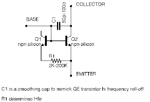 Replace the resistor with lugs 1 and 2 of a 200k trimmer or pot. (Lug 3 can be left unconnected.) Note that the collector and emitter of Q2 are the collector and emitter of the piggyback pair, and Q1 can be thought of as an add-on component. The cap is a so-called 'Miller cap'. It's purpose is to simulate the higher Miller capacitance of germanium transistors, which reduces the amplification of high frequencies. It softens the sound to help the silicon transistors sound more like germanium. You can play with the value to get the effect you want. The two 47p caps on the layout are the Miller caps. Measure the hfe of the piggyback pair with your DMM or the Geofex circuit (which you can set up on the same breadboard if you like. Adjust the trimmer and watch the hfe reading change. Dial it where you want it for the first stage, and remove the trimmer or pot without changing the setting. Measure the resistance between lugs 1 and 2 and set the resistance between the bottom two leads on the bottom trimmer to the same value, or just replace it with a fixed resistor. Keep track of which transistor is which. If you reverse them the piggyback hfe will change (although if your original transistors are matched, it probably won't change that much). Put Q1 from the breadboard in the Q2 place on the layout, and put Q2 from the breadboard in the Q1 place on the layout (obviously, the numbering is not the same for piggyback diagram and the layout). Now choose the desired hfe for the second stage and repeat the procedure. The second stage is Q3, Q4, and the bottom two legs of top trimmer. Note that Q1 on the breadboard is Q4 on the layout, and Q2 on the breadboard is Q3 on the layout. 2 (biasing). The conventional wisdom on classic-sounding NPN fuzz faces is that the Q2 collector (Q3 on the layout) should sit at 4.5V (the Eric Johnson version is biased to about 3.2V. Power up your circuit, turn the fuzz pot all the way up, and use your DMM to measure the DC voltage between ground and the collector of Q3. Use the bias pot to try to dial in a reading of 4.5V. If you chose piggyback gains near 80 and 120 for the first and second stages, then the 10K bias pot should get you there. If you went with higher gains, then you may have to use a higher value pot. Play through the circuit while changing the bias to see how it sounds at different bias points (the usual description is that lower biases sound splatty and gated, like ripping velcro, and higher biases sound more like hard edged distortion. Figure out what bias you like by ear. You might find that some bias points (particularly on the low end) cause the unit to go silent. If you want to experiment with different piggyback hfe's you'll have to do both steps over with different combinations of components. Once you get the hang of it, it goes pretty quickly. I hope this helps. Sorry for the wall of text, but as I said, unlike most vero layouts, this is not a paint-by-numbers circuit. In case it helps, here is the schematic I drew up for the one I built. It should be similar to the one IvIark used for his layout, except for a few mods. For example, I added a variable resistor in line with the input, and I added an inline biasing resistor chosen to limit the bias to the range I like. I noted the bias range and the hfe's of the individual transistors and the resulting piggyback pairs at the bottom. 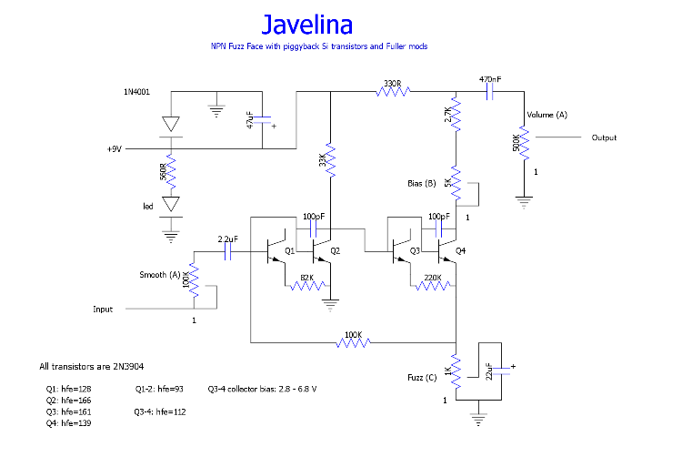 There's plenty more useful information at the links I provided in my first post. I recommend you read them, if you haven't already. Good luck. |
|
|
Induction - that is an excellent explanation, thank you for this - I've learned a little more after reading this
|
|
Administrator
|
Yes great info there buddy
|
Re: HELP cant get NPN germ emulation to work??
|
|
Indeed, good read.
Through all the worry and pain we move on
|
Re: HELP cant get NPN germ emulation to work??
|
|
In reply to this post by induction
Thank you very much for all your time and information on this circuit.I have learned alot about how this works.I found out why my circuit would not bias I had a bad bias pot.#1 lug was not working on it for some strange reason therefor it would not bias.I will be doing more testing with this circuit over the next few months to try and find different tones i like.Thank you again for all of your help.
|
«
Return to Open Chat
|
1 view|%1 views
| Free forum by Nabble | Edit this page |