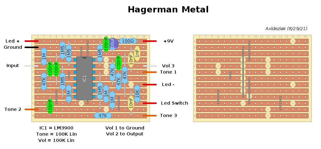
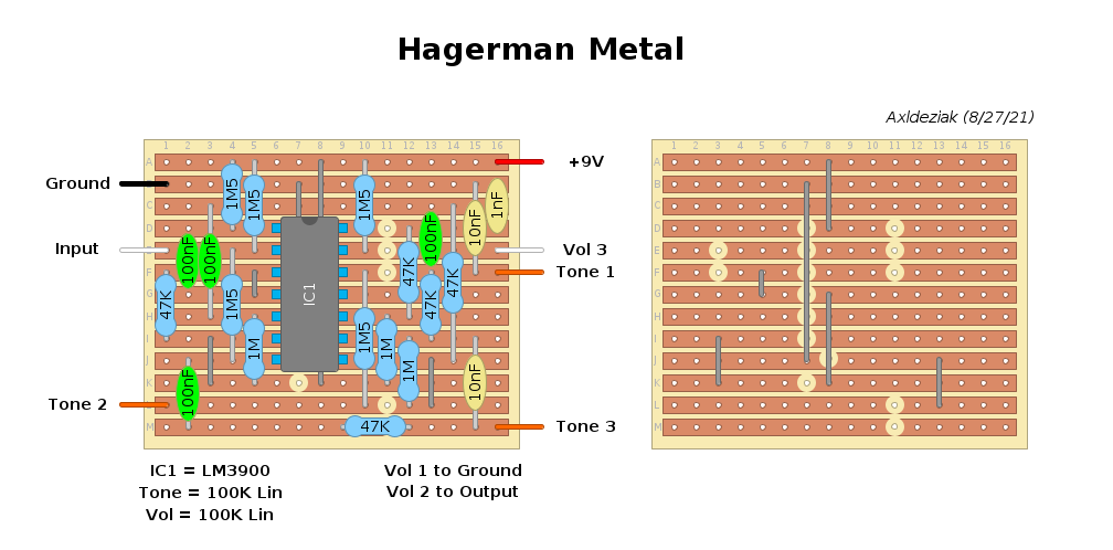
Hagerman Metal
|
Hi, I checked your layout. It seems good enough, but I think there's space, following the schematic, to include a 100R in line to the 9v and the 100nF and the 100uF across the ground.
There are a pair of things I can't get. I can't see the 1M pulldown resistor. And, in the schematic pin 2 is not shown. Link it to the VB is necessary? (Why two 1.5M?) So, it could be a 47uF to filter some noise, too.
I build pedals
|
|
It's pretty standard practice to just hang the pulldown resistor across the input jack.
I have a generic power filter board I put in things so I generally don't bother adding those parts to layouts. It's also not uncommon to just hang those parts across the power jack. The two extra 1M5 I put in there to terminate the unused section of the opamp to prevent noise. I used the 1M5 because the rest of the circuit uses them on the opamp input positives and if you were building it you'd have a pile of them handy. Using resistors this way is a best practice method for a single supply rail. That said, here's a layout with all the doodads.  |
The pulldown resistor "directly" across the input jack? Between tip and sleeve? In case, I guess it's not the best method, because the 1M will be across the ground even when the pedal is in bypass, so that's not a real true bypass. I think you can do it on the footswitch between the input of the circuit and the ground. I see it on some D*A*M pedal, I think. I prefer have those parts on the main board.  Totally clear.  Thanks for the new layout.
I build pedals
|
Your totally right. I've been thinking of the way amps are done. (But I know I've seen it multiple times... it must be a common error.) Moving forward I will remember that. Now I have a bunch of pedals to redo. 'oof Sly winks concern me. If I'm screwing up let me know. |
|
No, I'm seriously, it's ok. I thought, indeed, it was like you said, about the pin 2.
I build pedals
|
|
In reply to this post by Axldeziak
I know you've got this sorted, so please don't think of this as an argument. I just wanted to point out that, in addition to the 'not real true bypass' issue, pulldowns on the input jack don't actually pull anything down. When the circuit is in bypass, the pull down resistor is not connected to the input cap, which will still be floating. |
|
Thanks for pointing that out. I'll be sure to remember.
|
|
In reply to this post by induction
Thanks, man.
 There's anyway something "wrong" with a 1M or 2.2M resistor between signal and ground, even if it's pretty big. It isn't?
I build pedals
|
|
It's not ideal, but in most cases it will be sonically undetectable. Remember that a traditional volume control is just a big resistor to ground that gets tapped somewhere in the middle, and we have those built into the guitar. Also no material used in pedals is anywhere near perfectly resistive. So signal leaking to ground is unavoidable even without pulldowns. The trick is to make sure the leaks are small enough to be unnoticeable.
The sonic result of signal leaking to ground depends on how much current is available in the signal (aka source impedance). Passive pickups do not generate much current, so we go big with input pulldowns or passive input volume pots at 1M or higher. (Sometimes we actually want to bleed off treble or volume, in which case we use smaller values.) Directly after a buffer, the source impedance will be tiny, so we can often get away with much smaller pulldowns and output volume pots. 10k is a common value for output volume pots, but we usually stick with big output pulldowns for convenience, I guess. So if we have 10 pedals in our chain, and they are all wired with 1M pulldowns that are only visible to the signal when the circuit is engaged, then we should be fine. When the pedals are engaged, the pulldowns are all separated by active components that amplify the current, and the pulldowns don't add up cumulatively. But if the pulldowns are wired on the input jacks, then the signal sees all of them all the time. When the pedals are disengaged, we have an unbuffered 100k path to ground, which isn't horrible, but might be noticeable in some situations. If you look at a lot of pedal schematics, you'll see AC and DC leaks to ground all over the place. Sometimes it's intentional for signal shaping, and sometimes it's just required by the topology of the circuit. Circuit designers account for them in the tone shaping, and do a lot of ear testing to make sure the result is what they want. Think of it like this: if you have a pinhole leak in your water line, your shower will still work fine. If the hole is a couple of inches wide, you might not be able to rinse the shampoo out of your hair. |
«
Return to Unverified Layouts
|
1 view|%1 views
| Free forum by Nabble | Edit this page |


